


12
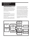
5 Theory of Operation
Keyboard Circuitry
The CADD-Prizm
®
pump is controlled by a
microprocessor. The actions of the micropro-
cessor are controlled by a program, which is
contained in the memory.
Commands are issued to the microprocessor
from the user via the nine keys on the key-
board and the Remote Dose cord. The keys on
the keyboard feed individually into the Gate
Array on the microprocessor board. A key
closure applies a ground to the associated
input of the Gate Array. Key debounce cir-
cuitry resident in the Gate Array provides a
clean output signal to the microprocessor for
the duration of the key closure. The micropro-
cessor reads keyboard status by accessing
special memory locations in the Gate Array.
The Remote Dose button consists of an SPDT
switch with its own dedicated input to the
microprocessor circuitry. The switch has a
common input line and two output signal
lines. The two signal lines are complementary
such that one line is always logic high and the
other is always low. When the Remote Dose
button is pressed, both signal lines change to the
alternate logic state. This redundancy prevents a
single line failure from starting a dose delivery.
Data Memory EEPROM
Many settings of the pump’s delivery and
record keeping parameters are stored by the
microprocessor in an Electrically Erasable
Programmable Read Only Memory
(EEPROM). Data to and from the memory is
presented serially. Whenever the microproces-
sor uses data from the EEPROM, the data is
checked for validity.
Battery Backed RAM
Additional settings of the pump’s delivery and
record keeping parameters are stored in a
battery backed Random Access Memory
(RAM). Battery backup is provided by two
printed circuit board-mounted lithium batter-
ies. These batteries are designed to provide a
minimum of five years of memory retention
during normal pump usage. Whenever the
microprocessor uses data from the RAM, the
data is checked for validity.
Time Base Circuitry
An accurate 3.6864 MHz timebase is provided
by a quartz crystal. The 3.6864 MHz signal is
connected to the microprocessor, where it is
frequency-divided to access the program
memory at a cycle rate of 921 kHz.
In addition, an accurate 32.768 kHz timebase
is provided by a second quartz crystal. The
32.768 kHz signal is used for the real time
clock.
LCD Circuitry
The high-impedance, low-power, special
drive signals for the liquid crystal display are
provided by the LCD-drivers. Each alpha or
numeric character on the LCD is formed by
darkening combinations of dots. Commands
to display dots are issued via data bus
commands to the LCD-drivers by the
microprocessor.
The LCD circuit also contains a power supply
which provides bias voltage to the LCD panel.
This voltage controls the relative brightness of
the characters. Additional circuitry allows the
microprocessor to disable the LCD when not
in use in order to conserve battery power.
A two brightness level LCD backlight is
provided to improve LCD viewing under low
light conditions. When the microprocessor
enables the LCD, it also enables the low
brightness backlight. Low brightness is used to
conserve battery power. If the AC adapter is
connected, the microprocessor will enable the
high brightness backlight since this does not
consume power from the battery.
The backlight automatically shuts off when the
LCD is turned off.