


13
LED Status Indicators
An amber and a green Light Emitting Diode
(LED) are provided under the pump’s front
panel overlay to provide pump status to the
user. Under software control, the LEDs can
either flash at a low duty cycle or be on con-
tinuously. A flashing indicator typically indi-
cates a normal mode of operation and a steady
“on” indicator typically indicates a fault
condition.
Flash PROM Technology
Program memory for the pump is stored in
Flash Programmable Read Only Memory
(Flash PROM). This type of memory allows
modification of the contents without physically
removing the device from the circuit board.
Under certain circumstances, the program can
also be downloaded through the I/O port on
the side of the pump. Several layers of redun-
dancy in the programming system prevent
accidental erasing or modification of the
PROM.
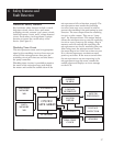
Gate Array Circuitry
The Gate Array contains circuitry which
controls memory address decoding, keyboard
debounce, Light Emitting Diode (LED) indica-
tor status, LCD command buffering, Battery
Backed RAM interface, and miscellaneous
signal line buffering functions.
Audible Alarm Circuitry
Audible alarm circuitry consists of a piezo
electric disk and independent oscillator. The
disk flexes or bends in resonance with the
output of the oscillator. The piezo disk is
mounted to the pump housing to enhance
sound level. The oscillator which drives the
piezo disk is capable of providing two driving
frequencies. The low frequency is in the range
of 700 to 1500 Hz and the high frequency is in
the range of 1600 to 2500 Hz. The micropro-
cessor controls the audible alarm via control
lines from the Gate Array. When the micropro-
cessor selects both the low and high frequency
control lines, the audible alarm enters a warble
mode where it oscillates between the low and
high frequency sound at a rate of 0.8 and 2
Hz. Low battery voltage detection and watch-
dog timer circuitry also have the ability to
enable the audible alarm via the Gate Array.
Watchdog Timer Circuit
Watchdog timer circuitry is provided to moni-
tor the status of the microprocessor and
disable the motor and enable the audible alarm
if the microprocessor fails to function properly.
The microprocessor must strobe the watchdog
circuit at least once every second in order to
prevent the watchdog from performing its reset
function. The reset output from the watchdog
circuit is a pulse output. This acts to “jump
start” the microprocessor. This unique feature
allows the microprocessor to test the watchdog
circuit on every power-up. By setting a flag in
memory and not strobing the watchdog, the
microprocessor can force a watchdog time-out.
After being reset, the microprocessor checks
the status flag to see if this was a time-out test.
If so, the microprocessor continues normal
power-up activities. If the reset occurred when
the microprocessor was not expecting it, the
microprocessor traps the event, sounds the
audible alarm and displays an error message
on the LCD.
Motor Driver/Motor Watchdog
Circuit
Motor drive circuitry is composed of a series of
power FET transistors, passive components,
and two voltage comparators. Built into the
motor drive circuitry is an RC timer which
times how long the motor runs each time it is
turned on. If the motor runs for more than an
average of 4 seconds, the circuit will time out
and disable the motor. A unique feature of this
circuit is that control lines to and from the
microprocessor circuit allow the microproces-
sor to perform a complete functional test of the
motor drive circuit without running the motor.
The microprocessor performs this test function
every several minutes to assure its continued
functionality. An input from the watchdog
circuit prevents motor operation if the watch-
dog timer expires.
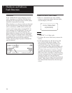
Rotation of the motor is sensed by the micro-
processor via an infrared-sensitive photo