


18
Motor Driver/Motor Watchdog Circuit
Motor drive circuitry is composed of a series of
power FET transistors, passive components,
and two voltage comparators. Built into the
motor drive circuitry is an RC timer which
times how long the motor runs each time it is
turned on. If the motor runs for more than an
average of 4 seconds, the circuit will time out
and disable the motor. A unique feature of this
circuit is that control lines to and from the
microprocessor circuit allow the microprocessor
to perform a complete functional test of the
motor drive circuit without running the motor.
The microprocessor performs this test function
every several minutes to assure its continued
functionality. An input from the watchdog
circuit prevents motor operation if the watch-
dog timer expires.
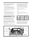
Cassette ‘Type’ Sensor Circuit
The cassette ‘Type’ sensor system consists of
three pins protruding from the button of the
pump mechanism that interface to the attached
administration set and associated circuitry.
Each type of administration set designed to
work with the CADD-Prizm
®
pump contains a
unique ‘code’ programmed into the set via
nubs molded into the plastic. When a set is
latched to the pump, the nubs press against the
pins in the pump mechanism in a pattern
unique to that set type. Optical detectors and
electronic circuitry on the circuit board encode
this pattern and report the information to the
microprocessor. This feature allows automatic
rate selection dependent on the type of set
attached. This system also acts as a safety
feature to detect a damaged or detached set.
If, during operation, the microprocessor
detects all pins extended, the pump will enable
audible and visual alarms and stop delivery.
Redundancy in the pattern prevents single fault
failures from causing over or under delivery of
fluid. Additional circuitry allows these sensors
to be turned on and off by the microprocessor
to conserve battery power. Additionally, control
of sensor power allows the microprocessor to
test the sensor inputs in both the powered and
unpowered states, thus allowing detection of
sensor fault conditions. Care should be taken
not to damage these sensor pins.
Latch/Lock Sensor Circuit
Latch and Lock sensors allow the microproces-
sor to detect the positions of the latch and lock
buttons. This prevents attempted fluid delivery
when the set is not correctly latched to the
pump. In addition, it allows the microprocessor
to stop fluid delivery and enable audible and
visual alarms if the set is unlatched during fluid
delivery. Opposing infrared transmitters and
receivers on both the latch and lock buttons
allow the microprocessor to detect their open
and closed positions. Additional circuitry
allows these sensors to be turned on and off by
the microprocessor to conserve battery power.
Additionally, control of sensor power allows
the microprocessor to test the sensor inputs in
both the powered and unpowered states, thus
allowing detection of sensor fault conditions.
Voltage Detector Circuit
Low voltage detection is performed by part of
the watchdog circuit and by the microprocessor
via software. Three low voltage levels are
detected. The first two levels are detected by
software and the third by hardware. The first
level to be reached is the Low Battery Warning
threshold which occurs when the battery
voltage decays to a nominal value of 6.8 volts.
An Analog to Digital Converter (ADC) built
into the microprocessor allows the micropro-
cessor, via software, to monitor the battery
voltage. At the Low Battery Warning thresh-
old, the microprocessor enables a periodic
series of beeps and displays a low battery
warning message on the LCD. As the battery
voltage reaches a nominal value of 6.3 volts,
the software disables delivery, places a battery
depleted message on the LCD, and enables a
constant two-tone audible alarm. When the
battery voltage decays to a nominal value of
5.6 volts, a hardware reset circuit is triggered
which places the microprocessor in reset. This
prevents ambiguous microprocessor operation
when the battery voltage continues to decay.
The hardware reset continues until the battery
is completely discharged or until it is removed.
Once the pump controller goes into low
battery shutdown, only replacing the old
battery with a fresh one will clear the condition.