


14
detector. An infrared light source is mounted
so that its light beam illuminates the infrared
detector. An opaque flag is mounted concentri-
cally to the camshaft and rotates with it be-
tween the infrared light source and detector.
When the flag interrupts the light beam, the
output of the detector is sensed by the micro-
processor via an input port bit. Power to the
infrared LED light source is controlled by the
motor driver circuit and is off when the motor
is not running to conserve battery life.
In the microprocessor software, multiple
checks are made on motion of the camshaft.
When the motor is commanded to start, the
infrared sensor must show that half a revolu-
tion has occurred within five seconds and that
the motor has stopped when half a rotation
was completed. In addition, no camshaft
rotation can take place when the motor has
not been commanded to run.
Power Circuitry
Power for the pump is normally supplied by a
9-volt alkaline battery, 9-volt lithium battery,
or AC adapter. These types of batteries have a
fairly low internal resistance over their dis-
charge range, which will keep power supply
noise low. Other types of batteries, such as
carbon-zinc, exhibit high internal resistance,
especially near depletion. A voltage drop
across the internal resistance occurs when
current is drawn by the motor during pump
activations. This current is demanded in short
pulses when the motor is first turned on and
generates large spikes in the battery voltage.
This noise can cause the low battery detection
circuit to shut down the pump.
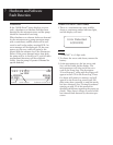
The motor driver circuit power is taken di-
rectly from the battery, but the microprocessor
and its associated circuitry requires closely
regulated and filtered 5-volt power which is
supplied from the micropower voltage regula-
tor. This regulator will supply 5-volt power
until its input voltage is approximately 5.3
volts. After that point, the output of the
regulator will follow the input voltage down.
Voltage Reference Circuit
A voltage reference circuit provides a constant
DC voltage to the microprocessor Analog to
Digital Converter (ADC). By reading this input
and comparing the value to a predetermined
range, the microprocessor can validate the
accuracy of the 5-volt power supply. Variations
in the 5-volt supply left undetected can result
in inaccuracy in the low battery alarm set
points and variations in other calculated values.
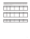
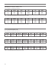
Table 12. CADD-Prizm
®
pump low battery conditions.
Voltage CADD
®
Pump Status
Trip Point*
>7.0V No alarm
6.4–7.0V* Transition to low battery
condition; battery low
message appears; 3 beeps
every 5 min.
†
6.0–6.6V* Transition to depleted
battery condition; battery
depleted message appears;
continuous alarm
††
5.25–5.95V Hardware reset occurs.
Pump continues to indicate
depleted battery condition.
* Voltage ranges are due to component
tolerances. Actual trip values are guaran-
teed to be non-overlapping.
† The pump emits 3 beeps every 5 minutes, and the
message “9 Volt Battery Low” appears on the pump’s
display, indicating that the battery power is low, but the
pump is operable.
†† The pump emits a continuous, variable-tone alarm,
and the message “9 Volt Battery Depleted” appears on
the display, the battery power is too low to operate the
pump, and pump operation has stopped.
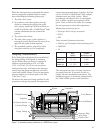
Pumping Mechanism
The pumping mechanism is linear peristaltic
with two active valves. Pumping occurs when
the expulsor presses on the reservoir pump
tubing in sequence with the inlet and outlet
valves. At rest, the outlet valve is pressing
down fully on the tubing and the expulsor and
inlet valve are retracted. (See Figure 7.)