


I.B. 29C892B
Page 5
Effective 8/99
2. If none of the pushbuttons on the operator panel are
used for approximately 2 1/2 minutes, the program-
mer turns itself off. This includes the performance of
a non-trip test. External power is required to perform
a trip test. Refer to the next paragraph for external
power details.
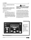
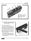
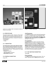
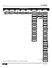
2-2.2 EXTERNAL CONNECTIONS
Three receptacles are provided on the top of the device,
one for an external power connection and two different
means for connecting the programmer to the trip unit
(Figure 2-2).
External Power Connection
Use external power to:
• Save internal battery power
• Perform trip test on circuit breaker
• Communicate over INCOM
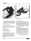
External power is provided by connecting an Auxiliary
Power Module (Catalog Number PRTAAPM) to the
OPTIMizer through the 2-pin male receptacle. The
Auxiliary Power Module requires a 120 Vac 50/60 Hz
input and delivers a 32 Vdc 4 VA output (Figures 2-2
and 2-5). Note that OPTIM trip units with external
power connections (K, L and N) operate from a 24 Vdc
power source.
Figure 2-4 OPTIMizer Battery Compartment with
Battery Installed
Figure 2-5 Auxiliary Power Module Shown Connected
to OPTIMizer
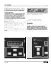
Direct Breaker Connection
The first method for connecting the hand held program-
mer to the trip unit is by means of the 8 conductor cus-
tom phone cord provided with the programmer. One end
plugs into the front panel of the trip unit and the other
end into a custom phone jack port (HDR1) on the top of
the programmer. This direct connection is intended only
for use with the hand held programmer, and is normally
associated with the direct programming of individual trip
units (Figures 1-1, 2-2 and 2-6).
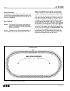
Network Connection
The second means for connecting the hand held pro-
grammer is through the 3-pin male connector (J2) locat-
ed on the top of the programmer. This connection is
made through an INCOM shielded twisted-pair. The
hand held programmer has an internal INCOM trans-
former permitting it to communicate over the network.
This is the method normally associated with network pro-
gramming (Figure 2 - 2). Auxiliary power to the OPTIMizer
is required to communicate over the INCOM network.
Notice: A direct connection will override an INCOM
connection. This will also signal a no response
alarm on other network devices.