


I.B. 29C892B
Page 11
Effective 8/99
SECTION 3: OPERATION AND USE
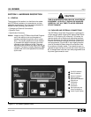
3-1 GENERAL
This section specifically describes the effective operation
and functional use of the OPTIMizer Hand Held Pro-
grammer. The OPTIMizer is used to access the many
capabilities of OPTIM 550, 750 and 1050 Trip Units.
Specific details associated with the trip units are covered
in Instruction Book 29C891 entitled “Instructions for
Installation, Operation and Maintenance of Cutler-
Hammer Digitrip OPTIM Trip Units.” It is recommended
that the operator review the material presented in
Section 2 prior to operating and using the hand held pro-
g r a m m e r .
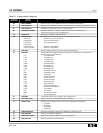
Familiarization with the information presented in Table
2 . 1 will prove helpful. Table 2 . 1 outlines the menu items
accessed from the top level menu (Figure 2 - 9 ). Menu
item definitions are provided in the user friendly display
with additional explanatory information provided in Table
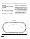
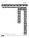
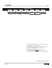
2 . 1 . In addition, an OPTIMizer Menu Diagram provides
an overall picture of the device’s capabilities (Figure 3 - 1 ) .
This diagram is also shown on the OPTIMizer back
panel for quick and easy reference (Figure 2 - 4 ) .
Section 3 covers the operation and use of the OPTIMizer.
It is broken down into the following general categories:
• Getting Started
• Power Application
• Security Password
• Assign Address/Select Baud Rate
• Configure Trip Unit
• Displayed Information
• Test Trip Unit
3-2 GETTING STARTED
The OPTIMizer Hand Held Programmer is a simple to
use device. Before applying power and using the
device, it is recommended that the following preliminary
steps be taken:
Step 1: If the programmer is to be operated by battery
power only, be sure that a fresh battery is
properly installed. Refer to paragraph 2-2.1 for
battery information.
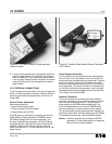
Step 2: If power will be supplied by an Auxiliary Power
Module, be certain that the Auxiliary Power
Module is connected to the appropriate 120
Vac source and the OPTIMizer Hand Held
Programmer. Refer to paragraph 2-2.2 for
details on an external power connection.
Notice: Keep in mind that an Auxiliary Power Module
is always required if a “Trip” Test is to be per-
formed on a circuit breaker.
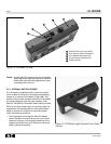
Step 3: When a Direct Breaker Connection is being
made, plug either end of the custom phone
cord into the phone jack port on the top of the
programmer first, and then plug the other end
into the port provided on the trip unit. The con-
nections should be made before power is
applied. Refer to paragraph 2-2.2 for details on
a Direct Breaker Connection.
Notice: A direct breaker connection will override an
INCOM connection. This will also signal a no
response alarm on other network devices.
Clear the alarms when finished.
Step 4: If a Network Connection is being made using
an INCOM twisted-pair connection to the 3-pin
connector located on the top of the program-
mer, refer to paragraph 2-2.2 for details on a
Network Connection.
Step 5: No matter which connection approach is used,
be certain that all plug-in connections are
properly seated. This includes trip unit, exter-
nal power and INCOM connections to the pro-
grammer as well as connections from the pro-
grammer to the trip unit or INCOM.
The programmer is now ready to have power applied.
3-3 POWER APPLICATION
Turn the programmer on by holding the red On/Off
pushbutton in the depressed position for approximately
one second. Upon release of the pushbutton, the first
message will be displayed.
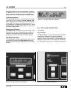
Three different types of messages can be displayed
before the top level menu appears (Figure 2-9). The
messages displayed will depend on the programmer
connection or lack of a proper connection as follows:
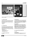
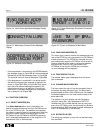
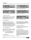
• If the programmer detects the lack of a proper con-
nection, two consecutive messages will be displayed.
Figure 3-2 shows the first message displayed while
the programmer searches for a compatible device. If
the programmer is unable to make a connection,
Figure 3-3 shows the second message that appears
momentarily before the top level main menu is dis-
played (Figure 2-9).