


I.B. 29C892B
Page v
Effective 8/99
LIST OF FIGURES
Figure Title Page
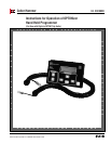
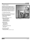
1-1 Hand Held Programmer in Use with Series C R-Frame Circuit Breaker ...................................................2
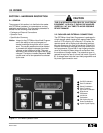
2-1 OPTIMizer Operator Panel........................................................................................................................3
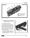
2-2 OPTIMizer Top View..................................................................................................................................4
2-3 OPTIMizer Hinged Protective Cover (Open Position)................................................................................4
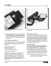
2-4 OPTIMizer Battery Compartment with Battery Installed ............................................................................5
2-5 Auxiliary Power Module Shown Connected to OPTIMizer.........................................................................5
2-6 OPTIMizer Shown Connected to Series C L-Frame Circuit Breaker.........................................................6
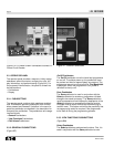
2-7 General Pushbuttons.................................................................................................................................6
2-8 View Functions Pushbuttons .....................................................................................................................7
2-9 Top Level Main Menu Display ...................................................................................................................7
2-10 Edit Values Pushbuttons ...........................................................................................................................7
2-11 Main Menu Options Screens .....................................................................................................................8
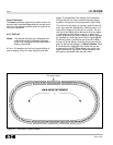
3-1 OPTIMizer Menu Diagram.......................................................................................................................12
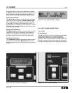
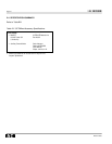
3-2 Initial Power Application Message Display..............................................................................................14
3-3 Momentary Connect Failure Message Display........................................................................................14
3-4 Address Invalid Display ...........................................................................................................................14
3-5 Typical Momentary Successful Connection Message Display ................................................................14
3-6 Cursor on Password in Main Menu..........................................................................................................14
3-7 Password Menu.......................................................................................................................................15
3-8 Present Valid Password Entry Screen.....................................................................................................15
3-9 Password Accepted Display....................................................................................................................15
3-10 Password Error Display...........................................................................................................................15
3-11 Password Change Display.......................................................................................................................15
3-12 Password Code Change Display.............................................................................................................16
3-13 Cursor on CHANGE BAUD/ADDR in Main Menu....................................................................................16
3-14 Present Baud Rate and Address Displayed ............................................................................................16
TABLE OF CONTENTS (Continued from previous page)
3-10 Copy and Download Commands.......................................................................................................................22
3-10.1 Using the Copy Command ...................................................................................................................22
3-10.2 Using the Download Command............................................................................................................22
3-11 Reset Trip Unit ..................................................................................................................................................22
SECTION 4: TROUBLESHOOTING AND MAINTENANCE
4-1 Level of Repair ..................................................................................................................................................23
4-2 Troubleshooting.................................................................................................................................................23
4-3 Maintenance and Care......................................................................................................................................23
4-4 Return Procedure..............................................................................................................................................23
4-5 Technical Assistance.........................................................................................................................................23
APPENDIX A INSTRUCTIONAL REFERENCES .....................................................................................................25