


I.B. 29C892B
Page 17
Effective 8/99
during use of the programmer. To accomplish this, fol-
low Steps 4 and 5 just outlined for Method 1.
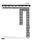
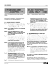
3-5.1 CHANGE SECURITY PASSWORD
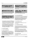
Step 1: With the programmer turned on and the main
menu displayed, use the Right-Arrow or Left-
Arrow pushbuttons to move the blinking cursor
to Password (PA) (Figure 3-6).
Step 2: Use the Select pushbutton to enter Password
(PA) (Figure 3-7).
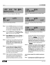
Step 3: Use the Left-Arrow pushbutton to select
=Change in the display. A screen that permits
entry of the present valid password is dis-
played (Figure 3-8).
Step 4: The blinking cursor indicates which of the four
displayed zeros is active and able to be altered.
Use the Edit Values U p or Down p u s h b u t t o n s
to change the active number. Use the R i g h t -
A r r o w or Left-Arrow pushbuttons to move the
cursor from one digit to another.
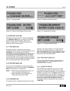
Step 5: Once the present password is displayed cor-
rectly, hold Save pushbutton depressed and
depress Select pushbutton. This simultaneous
use of the two pushbuttons will enter the pass-
word. If the password entered is valid, Pass-
word Accepted will be displayed (Figure 3-9).
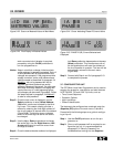
If the password is not valid, a Password Error
message will be displayed momentarily and
the display will automatically return to the main
menu (Figure 3-10).
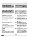
Step 6: If the password entered in Step 5 was valid,
Password Accepted will continue to be dis-
played until the Up-Arrow pushbutton of View
Functions is pressed and released. When the
pushbutton is used, Password Change is dis-
played (Figure 3-11). This display permits the
entry of a new password.
Step 7: The blinking cursor indicates which of the four
displayed zeros is active and able to be altered.
Use the U p or Down pushbuttons to change the
active number. Use the R i g h t - A r r o w or L e f t -
Arrow pushbuttons to move the cursor from one
digit to another.
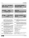
Step 8: Once the password displayed is as required,
hold Save pushbutton depressed and depress
Select pushbutton. This simultaneous use of
the two pushbuttons will enter the new pass-
word, and Password Code Change Being
Saved will be momentarily displayed (Figure 3-
12). When the new password is saved, the dis-
play automatically returns to the main menu.
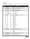
3-6 ASSIGN ADDRESS/SELECT BAUD RATE
The OPTIMizer Hand Held Programmer must be used
to initially establish the baud rates and unique address-
es of connected circuit breakers. Assigning or changing
circuit breaker addresses and/or baud rates takes place
within the same category of the main menu, Change
Baud/Addr (BA). Each circuit breaker must have a
unique address with all addresses containing three dig-
its. The three digit address will be in a HEXADECIMAL
Format with choices of 0 through 9 and A through F.
The two baud rate choices are 1200 or 9600, displayed
as 96B or 12B.
Notice: All circuit breakers are supplied from the facto-
ry with a 9600 baud rate “96B” and an address
of “FFE” (Hex Form) already programmed.
Keep in mind, however, when assigning
addresses, the Breaker Interface Module will
only recognize addresses at or below 32 HEX
(two digits).
3-6.1 DIRECTLY CONNECTED BREAKER ADDRESS
AND BAUD RATE
Use the following steps as a guide to assigning or
changing addresses and selecting baud rates when the
programmer is directly connected to a circuit breaker:
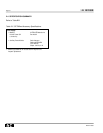
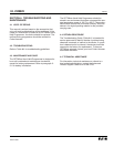
Figure 3-15 Address/Baud Rate Change Accepted
Display
CHANGE BAUD/ADDR
*** ACCEPTED ***
Figure 3-16 Network Address Selection Display
SELECT ADDRESS
INCOM ONLY 000