


I.B. 29C892B
Page 21
Effective 8/99
grammer on. If the programmer is directly con-
nected to a trip unit, it will momentarily identify
the baud rate and address, and move to the
main menu (Figure 2-9). If the programmer is
INCOM connected, proceed with Steps 2, 3
and 4, otherwise move directly to Step 5.
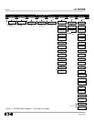
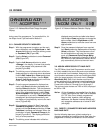
Step 2: Once the main menu is displayed, use the
Select pushbutton to enter Se l e c t Ad d r e s s
( S A ) which is active as indicated by the blinking
cursor. This network display provides a means
for selecting the three digit address of the circuit
breaker of interest within the network (Figure 3 -
1 6 ). The blinking cursor indicates which of the
three digits is active and able to be changed.
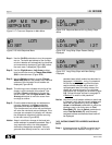
Step 3: Use the Up or Down pushbuttons to change
the active digit. Use the Right-Arrow or Left-
Arrow pushbuttons to move the cursor from
one digit to another.
Step 4: Once the desired breaker address is displayed,
hold Save pushbutton depressed and depress
Select pushbutton. This simultaneous use of
the two pushbuttons will enter the address of
the circuit breaker in question, and the main
menu will be displayed.
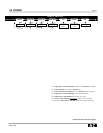
Step 5: Use the Right-Arrow or Left-Arrow pushbut-
tons to move the cursor to Metered Values
(ME) in the main menu (Figure 3-22).
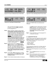
Step 6: Use the Select pushbutton to enter Metered
Values (ME) and the first four metered values
are displayed with the blinking cursor indicating
that Phase A Current is active (Figure 3-23).
Step 7: Use the Right-Arrow or Left-Arrow pushbut-
tons to move the blinking cursor to a metered
value of interest, Phase B current for example
(Figure 3-24).
Step 8: Use the Select pushbutton to choose the
metered value of interest and have the present
value displayed (Figure 3-25).
Step 9: Repeating Steps 7 and 8 will permit the view-
ing of all the metered values outlined in Table
2.1.
Step 10: Use the Up-Arrow pushbutton to return to the
main menu (Figure 2-9).
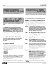
3-9 TEST TRIP UNIT
Digitrip OPTIM 550, 750 and 1050 Trip Units contain a
test capability. One of the means for performing tests is
through the use of the OPTIMizer Hand Held Program-
mer. The intent is to permit the periodic performance of
tests that verify the functional performance of the trip
unit. Two types of testing are possible through the use
of the OPTIMizer Hand Held Programmer, the “No-Trip”
and the “Trip” tests.
No-Trip Test: This test can be performed using the
internal battery power of the programmer. It verifies that
the trip unit is performing under test within acceptable
limits of the programmed protective setpoints.
Trip Test: This test can only be performed using exter-
nal power supplied by an Auxiliary Power Module or by
auxiliary power supplied to the circuit breaker. The addi-
tional power is required to activate the breaker’s flux
transfer shunt trip. This test verifies the trip unit’s perfor-
mance, as well as the trip circuitry and mechanical oper-
ation of the circuit breaker.
Notice: Keep in mind that an Auxiliary Power Module is
required to perform a “Trip” test. Refer to para-
graph 2-2.2 for details on the use of an
Auxiliary Power Module.
Notice: Basic protection functions are not affected dur-
ing the performance of testing procedures.
Proceed with the following steps to perform a “Trip” or a
“No-Trip” test:
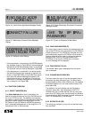
Step 1: With the programmer turned on and the main
menu displayed, use the Right-Arrow or Left-
Arrow pushbuttons to move the blinking cursor
to Test Mode (TM) (Figure 3-26).
Step 2: Use the Select pushbutton to enter the Test
Mode (TM). The blinking cursor indicates
which test category is active and able to be
selected (Figure 3-27).
Step 3: Use the Right-Arrow or Left-Arrow pushbut-
tons, if required, to move the blinking cursor to
a different test category. Use the Select push-
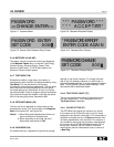
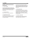
Figure 3-32 Typical Cause of Trip Message
SHORT DELAY TRIP
TRIP TIME .03s