


I.B. 29C892B
Page 20
Effective 8/99
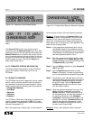
(SP) option. Method 1 or Method 2 can be
used to enter a valid password, although
Method 1 is recommended. Directions on how
to enter a password will not be given in the fol-
lowing steps covering setpoint changes.
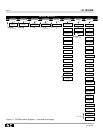
Step 3: Once a valid password is entered and accept-
ed, use the Right-Arrow or Left-Arrow push-
buttons to move the blinking cursor to
Setpoints (SP) (Figure 3-17).
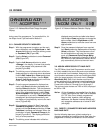
Step 4: Use the Select pushbutton to enter Setpoints
(SP) (Figure 3-18). The blinking cursor indi-
cates which programmable category is active
and available for programming. The second
line of the display defines the active category.
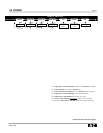
Step 5: Use of the Right-Arrow or Left-Arrow push-
buttons to move from one programmable cate-
gory to another (Figure 3-19).
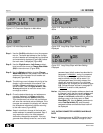
Step 6: Use the Select pushbutton to enter an active
category, such as Long Delay Slope (Figure
3-20). The present programmed setpoint for
Long Delay Slope is I
2
t, for example.
Step 7: Use the Up or Down pushbuttons to establish
a new setpoint, such as I
4
t (Figure 3-21).
Step 8: Hold Save pushbutton depressed and depress
Select pushbutton. This simultaneous use of
the two pushbuttons will enter the new setpoint
into memory.
Notice: Keep in mind that changes must be saved indi-
vidually to minimize the possibility that re-pro-
gramming would be required if the programmer
turns itself off during the programming process.
Step 9: All setpoint changes are made using the same
repetitive steps just described.
3-8 DISPLAYED INFORMATION
The OPTIMizer Hand Held Programmer displays a com-
prehensive list of:
• Circuit Breaker Information
• Time-Current Setpoints
• Metered Values
• Trip Event Information
Use the following steps as a guide for obtaining specific
displayed information:
Step 1: Use the On/Off pushbutton to turn the pro-
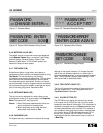
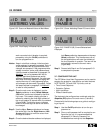
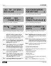
Figure 3-26 Cursor on Test Mode in Main Menu
<BA RP ME TM>
TEST MODE
Figure 3-27 First Display in Test Mode
PHASE GND
**PHASE TEST**
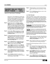
Figure 3-29 Momentary Notice Displayed
AUX.POWER NEEDED
FOR TRIP TEST
Figure 3-30 Momentary Notice Displayed
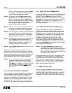
Figure 3-31 Displayed Choice After Trip or No Trip
Figure 3-28 Displayed Choices After Phase or Ground
TRIP< >NO TRIP
**TRIP**
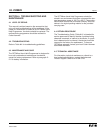
GETTING
FRAME/PLUG VALUE
ENTER CURRENT IN
AMPS 400