


I.B. 29C892B
Page 19
Effective 8/99
work connected circuit breaker is required,
proceed by using the On/Off pushbutton to
turn the programmer on.
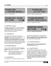
Notice: Keep in mind that a change in the baud rate
and/or address is password protected. Entry of
a valid password will be required before any
changes are accepted. If the programmer was
already turned on, and a valid password was
initially entered as described in paragraph 3-4
Method 1, entry of a password will not be
required again and the baud rate and/or
address changes will be saved. If a valid pass-
word was not initially entered, the display will
require the entry of a valid password before
any changes can be saved (Figure 3-8). Follow
the steps outlined in paragraph 3-4 Method 2
to enter a valid password.
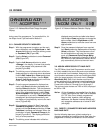
Step 2: Once the main menu is displayed, use the
Select pushbutton to enter Select Address
(SA) which is active as indicated by the blink-
ing cursor. This network display provides a
means for selecting the three digit address of
the circuit breaker of interest within the network
(Figure 3-16). The blinking cursor indicates
which of the three digits is active and able to
be changed.
Step 3: Use the Up or Down pushbuttons to change
the active digit. Use the Right-Arrow or Left-
Arrow pushbuttons to move the cursor from
one digit to another.
Step 4: Once the desired breaker address is displayed,
hold Save pushbutton depressed and depress
Select pushbutton. This simultaneous use of
the two pushbuttons will enter the address of
the circuit breaker in question. The user will be
automatically returned to the main menu
(Figure 2-9).
Step 5: Proceed with Step 4 and 5 of paragraph 3-5.1
to complete the process.
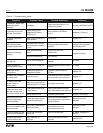
3-7 CONFIGURE TRIP UNIT
The OPTIMizer Hand Held Programmer can be used to
program the protective, coordination and alert features
of OPTIM 550, 750 and 1050 Trip Units, such as:
• Time-Current Setpoints
• Protection Options
• High Load Alarm
• Phase A Identification
The features to be configured are contained under the
Setpoints (SP) option of the main menu (Table 2.1).
Proceed with the following steps as a guide to configur-
ing a trip unit:
Step 1: Use the On/Off pushbutton to turn the pro-
grammer on.
Step 2: Since a valid password will be required to con-
figure the trip unit, it is recommended that
paragraph 3-4 “Security Password” be
reviewed before moving into the Setpoints
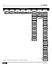
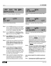
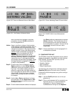
Figure 3-22 Cursor on Metered Values in Main Menu
<ID BA RP ME>
METERED VALUES
IA IB IC IG
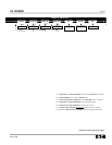
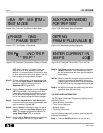
PHASE B
Figure 3-25 PHASE B (IB) Current Selected and
Displayed
Figure 3-24 Cursor Indicating Phase B Current Active
IA IB IC IG
PHASE B 600
IA IB IC IG
PHASE A
Figure 3-23 First Display in Metered Values