


I.B. 29C892B
Page 15
Effective 8/99
3-4.6 METERED VALUE (ME)
The phase, neutral and ground currents are displayed
in the Metered Values menu, as well as Total Energy,
Forward Energy, Reverse Energy, Power, Peak
Demand, Power factor, %THD of each phase, and
Harmonic Content of each phase.
3-4.7 TEST MODE (TM)
Simulations of either a long delay, short delay, or
instantaneous fault condition can be performed by using
Test Mode. This can be done by first reading
the setpoints and noting their adjustment. The trip mode
menu item can then be selected and a current above
the noted settings can be entered. A trip or no trip test
can be performed. A test in progress may be terminated
if the currents through the breaker under test are above
40% of the rating plug value. See section 3-9.
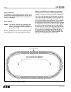
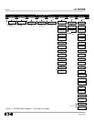
3-4.8 SETPOINTS MENU (SE)
The trip unit can be adjusted for various time-current
characteristic curves. This is done within the Setpoints
Menu. See section 3-7, and Figure 3-1.
Notice: 1) Short Delay and Instantaneous Action can
not be turned off at the same time.
2) When long delay is set to I
4
t, the short
delay slope must be set to Flat.
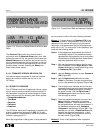
3-4.9 PASSWORD (PA)
For system security, a password is required to change
settings or use certain features. To change the baud
rate or trip unit address, setpoints, run test mode, or
download copied setpoints, a correct password must be
used. The OPTIMizer’s factory default setting is 1000.
See section 3-5 for additional details.
3-4.10 TRIP EVENT COUNT (TC)
The trip unit records the number of times that the trip
unit has initiated a trip. This is displayed when the
Trip Event Count is selected.
3-4.11 CAUSE OF TRIP (CT)
The OPTIMizer can display the cause of trip, similar
to the cause of trip LEDs of the trip unit, but in some
cases with more specific information. This information is
available as long as the trip unit Reset pushbutton has
not been pressed after a trip condition. For example, a
non-compliant rating plug may cause an instantaneous
trip to occur which will light the Instantaneous LED of
the trip unit. However, the OPTIMizer in this case
would display that the instantaneous trip is a result of
a Bad Plug.
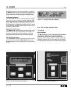
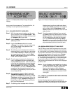
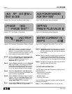
Figure 3-9 Password Accepted Display
*** PASSWORD ***
*** ACCEPTED***
Figure 3-10 Password Error Display
*PASSWORD ERROR*
ENTER CODE AGAIN
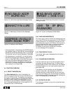
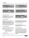
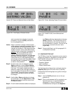
Figure 3-7 Password Menu
PASSWORD
<=CHANGE ENTER=>
Figure 3-8 Present Valid Password Entry Screen
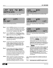
Figure 3-11 Password Change Display
PASSWORD CHANGE
SET CODE 0000
PASSWORD ENTER
SET CODE 0000