


1. HOW TO INSTALL THE SYSTEM
1-13
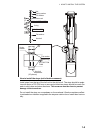
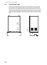
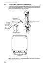
1.5 IF Unit
Refer to the outline drawing at the back of this manual for mounting dimensions. Fas-
ten the unit with 5×20 self-tapping screws. If the unit is to be installed on a bulkhead,
be sure that the location does not allow water to drip into the cable entrance.
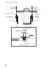
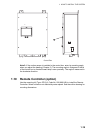
1.6 Attachment Kit (option)
The attachment kit permits use of the retraction tank for the CSH-80 series.
OP10-30. Code No. 000-067-179
1. Clean the flange and O-ring groove of the retraction tank (welded to hull) with ethyl
alcohol moistened waste cloths. Coat O-ring and O-ring groove with lithium
grease. Place the O-ring in its groove on the tank flange.
2. Lay the insulation gaskets (1) on the top of the tank flange.
3. Position the hull unit so that the bow mark (inscribed) on its flange points toward
the ship's bow. Note that heading adjustment in the monitor is required if the bow
mark does not physically face the ship's bow.
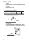
4. Confirm the following points as below and place the hull unit on the tank.
• Clean the flange platform.
• Wipe the undersurface of the hull unit flange with clean waste cloths.
• Keep O-ring in its groove.
5. Insert the flat washers and insulation gaskets (2) into the bolt holes of the tank
flange.
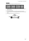
6. Coat threads of the bolts with a slight amount of lithium grease to prevent scorch-
ing. Insert the bolts with washers from the retraction tank flange, and then put the
flat washers and spring washers in this order from above. Fasten bolts with nuts.
Name Type Code No. Qty
Insulation Gasket (1) SHG-0003-1 100-038-571 1
Insulation Gasket (2) MS-1000-68-1 100-347-611 16
O-ring C00117A 000-158-976-10 1