


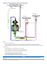
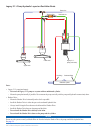

21GHP 10 Marine Autopilot System Installation Instructions
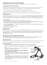
When the shutoff valve is engaged, the boat will steer normally, and the pump will not control the steering system. When the shutoff
valve is engaged, you can remove the pump from the system for repair without disconnecting any hydraulic lines.
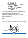
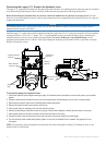
To remove the pump from the shutoff-valve manifold:
1. Tighten the three brass screws near the lower hydraulic connectors.
2. Remove the four socket-head cap screws that connect the manifold to the pump.
3. When the manifold is no longer connected to the pump, the pump can be disconnected from the ECU and removed from its
mounting location. The hydraulic steering system will operate normally.
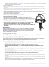
To reconnect the pump to the shutoff-valve manifold:
1. Remount the pump and reconnect the pump to the ECU.
2. Connect the manifold to the pump using the four socket-head cap screws.
3. Loosen the three brass screws near the lower hydraulic connectors until they stop. Do not loosen the screws past the stopping
point.
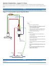
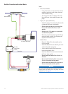
Connecting the Pump to the ECU
Do not connect the pump to the ECU until you have mounted the ECU to the boat following the procedures on page 25.
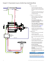
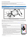
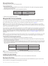
Installing an Unbalanced Kit on a 1.2 L or 2.0 L Pump
If your boat has an unbalanced cylinder steering system, then you need to install the optional unbalanced kit (Garmin part number
010-11201-00).
To install the unbalanced kit:
1. Loosen and remove the four screws that hold the manifold to the pump body. Remove the manifold from the pump body.
2. Replace the O-rings on the pump body with the O-rings supplied in the unbalanced kit.
3. Place the unbalanced valve between the pump body and the manifold, with the O-rings on the unbalanced valve facing the
manifold. There are six O-rings: three on the pump body, and three on the unbalanced valve.
4. Use the four longer screws included in the unbalanced kit to connect the manifold and unbalanced valve to the pump body. Use
thread-locking compound and tighten the screws to 35 lbf-in (3.95 N-m) of torque.
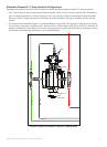
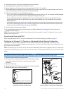
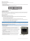
Adjusting and Calibrating the Unbalanced Valve
The brass screws on the sides of the unbalanced valve adjust the valve. Compare the amount of screw protruding beyond the valve
body on both sides of the valve. Both screws should protrude the same distance. To recalibrate the screws, fully tighten both of them
until they stop. Be sure they protrude the same distance after they stop. If not, loosen the shorter screw until they protrude the same
distance. Unscrew each screw by two and one-half turns. The valve is ready for use.
Notice
Do not unscrew the brass screws more than the specied amount. Do not operate the system with the brass screws fully tightened.