


27GHP 10 Marine Autopilot System Installation Instructions
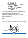
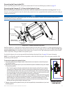
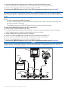
Wiring the Shadow Drive
Wire the Shadow Drive to the CCU/ECU interconnect cable.
To wire the Shadow Drive:
1. Route the bare-wire end of the CCU/ECU interconnect cable to the Shadow Drive. If the cable is not long enough, extend the
appropriate wires with 28 AWG wire.
2. Use the Shadow Drive Wiring Table to make the appropriate connections.
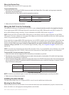
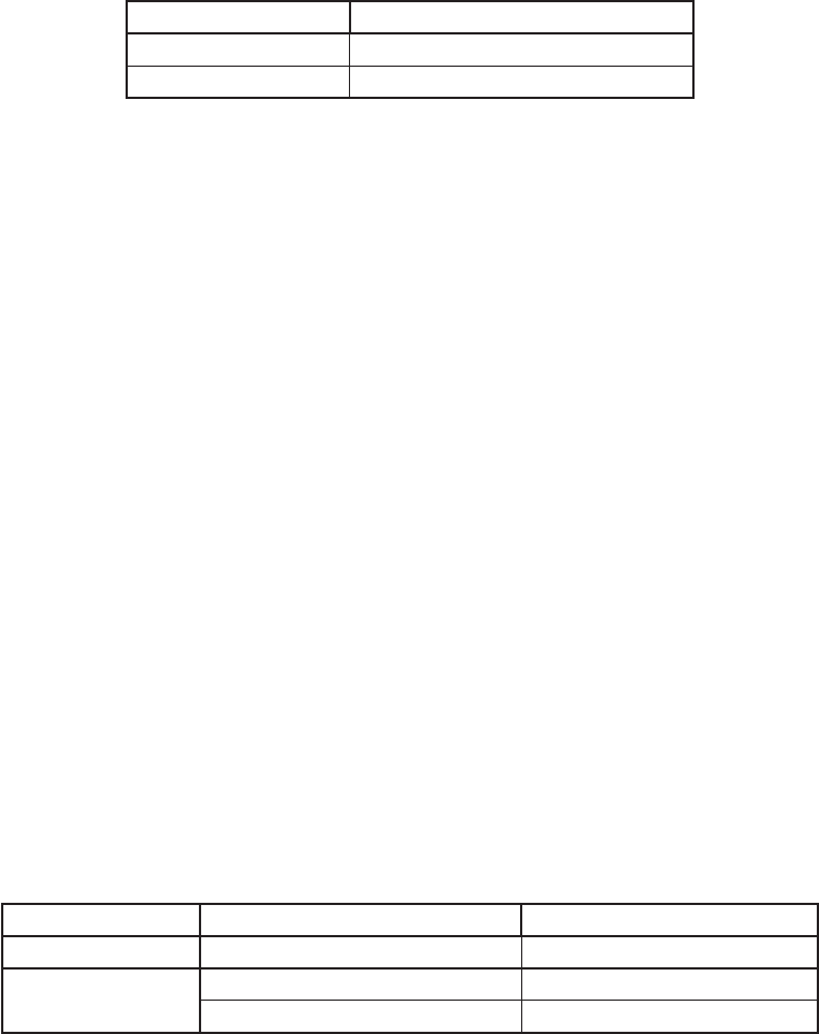
Shadow Drive Wire Color CCU/ECU Interconnect Cable Wire Color
Red (+) Brown (+)
Black (-) Black (-)
Shadow Drive Wiring Table
3. Solder and cover all bare-wire connections.
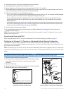
Wiring the GHP 10 to the Tachometer
The tachometer connection is an important part of the GHP 10 system, and must be wired correctly for the autopilot to function.
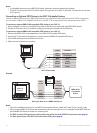
If your engine supports NMEA 2000 engine data, and is connected to the same NMEA 2000 network as the GHC 10 and the CCU,
then no other tachometry wiring is necessary. For more information on the NMEA 2000 network, see page 30.
NOTE:
Mercury and Volvo offer add-on NMEA 2000 gateways to share Mercury and Volvo engine information over the NMEA
2000 network. If you have a Mercury or Volvo engine, these adapters provide the easiest installation and the most reliable engine data
transfer. See your marine dealer for more details.
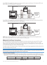
If your engine does not support NMEA 2000 engine data, then wire the GHP 10 autopilot system to the tachometer of your boat using
the bare-wire portion of the CCU/ECU interconnect cable. In most cases, this connection can be made behind the dashboard at the
tachometer display. Refer to the owner’s manual or shop manual for your engine to identify the color codes and location of the
tachometer wiring on your boat. For a list of common engine tachometry wiring, visit www.garmin.com/ghp10/ and click on the
manuals link.
NOTE:
If your boat uses an electrical system that provides more than 12 Vdc, or if you sporadically receive tachometer errors, install
an external tachometer lter (010-11399-00). Contact your local Garmin dealer or Garmin product support for more information.
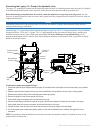
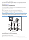
To wire the GHP 10 to the tachometer of your boat:
1. Identify the location and wire assignments of the tachometer (or tachometers) on your boat.
2. Route the bare-wire end of the CCU/ECU interconnect cable to the tachometer (or tachometers). If the cable is not long enough,
extend the wires with twisted pair, 22 AWG wire.
3. Use the Tachometer Wiring Table to determine the appropriate wires on the CCU/ECU interconnect cable. Connect the tachometer
wire or wires from the CCU/ECU interconnect cable to the tachometer sensor wire or wires from the engine (or engines). Connect
the ground wires to a clean ground.
Engine Conguration Tachometer Ground
Single engine Green and violet (twist together) White and grey (twist together)
Dual engines Port engine = violet Port engine = grey
Starboard engine = green Starboard engine = white
Tachometer Wiring Table
NOTE: For three or more outboard engines, connect to the outermost port and starboard engines, according to the table.
4. Solder and cover all bare-wire connections.
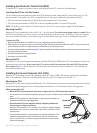
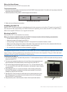
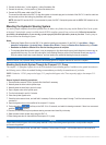
Installing the Alarm Buzzer
The alarm buzzer audibly alerts you to important GHP 10 events. It must be installed near the helm station.
Mounting the Alarm Buzzer
Mount the alarm buzzer near the helm station. You can mount the alarm buzzer under the dashboard if you prefer. Secure the alarm
buzzer with cable ties or other appropriate mounting hardware (not included).