


32 GHP 10 Marine Autopilot System Installation Instructions
Notes:
To add additional sensors to your NMEA 2000 network, follow the instructions included with the sensor.
The GHC 10 must connect to the CCU with the yellow CCU signal wire in the GHC 10 data cable. The black wire must connect
to CCU ground.
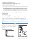
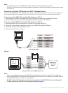
Connecting an Optional GPS Device to the GHP 10 Autopilot System
Connect an optional GPS device to the NMEA 2000 network to use waypoint and route information with the GHP 10. Alternatively,
you can connect a NMEA 0183-compatible GPS device to the GHC 10 to use waypoint and route information with the GHP 10.
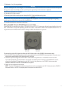
To connect an optional NMEA 2000-compatible GPS device to your GHP 10:
1. Add an additional T-connector (not included) for the optional GPS device you want to add to the NMEA 2000 network.
2. Connect the GPS device to the T-connector by following the instructions provided with the GPS device.
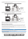
To connect an optional NMEA 0183-compatible GPS device to your GHP 10:
1. Determine the NMEA 0183 wiring assignments of your NMEA 0183-compatible GPS device.
2. Use the GHC 10 data cable wiring diagrams to correctly wire your NMEA 0183-compatible GPS device.
3. Use 22 AWG twisted-pair wire for extended runs of wire.
4. Solder and cover all bare-wire connections.
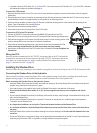
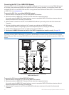
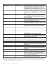
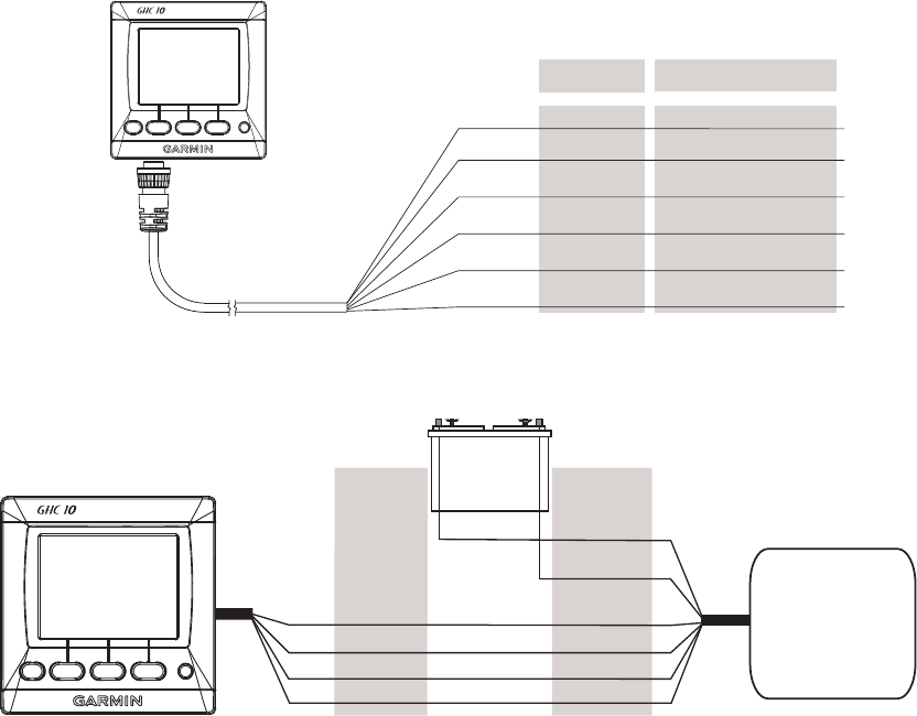
GHC 10 Data Cable
>
>
>
>
>
GHC 10
Device
Color Function
CCU Signal
Tx/A(+)
TX/B(-)
Rx/A(+)
Rx/B(-)
Yellow
Blue
White
Brown
Green
CCU Signal Ground
Black
Example:
>
>
>
>
>
>
>
>
+
-
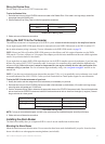
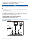
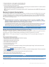
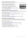
Wiring the GHC 10 to a NMEA 0183 Device
BROWN
GREEN
WIRE
COLOR
WIRE
FUNCTION
POWER
NMEA GND
Tx/A (+)
Tx/B (-)
NMEA 0183-
Compatible
Device
GHC 10
Device
Battery
12 Vdc
BLUE
WHITE
Rx/A (+)
Rx/B (-)
Notes:
Consult the installation instructions for your NMEA 0183-compatible device to identify the Transfer (Tx) A(+) and B(-) wires.
When connecting NMEA 0183 devices with two transmitting and two receiving lines, it is not necessary for the NMEA 2000 bus
and the NMEA 0183 device to connect to a common ground.
The GHC 10 yellow (CCU signal) wire must be wired to the yellow wire of the CCU/ECU interconnect cable (page 6).
The black (ground) wire of the GHC 10 must be wired to CCU ground (page 6).
•
•
•
•
•
•