


5GHP 10 Marine Autopilot System Installation Instructions
Installation Preparation
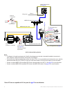
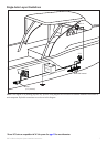
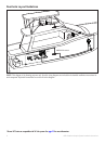
Before installing the GHP 10 autopilot system, it is important for you to completely understand where all the components will be
located on your boat. Temporarily place all the components where you plan to install them. Ensure that all cables and hydraulic hoses
can reach the necessary components before mounting any components.
NOTE:
There is an installation checklist on the last page of these instructions. Remove the last page and refer to the checklist as you
proceed through the GHP 10 installation.
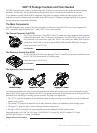
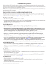
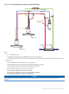
Electrical/Data Connection and Mounting Considerations
The GHP 10 components connect to each other and to power using the included cables. Ensure that the correct cables reach each
component and that each component is in an acceptable location before mounting or wiring any components. Read the following
considerations and consult the diagrams on pages 6–8 before you begin installation.
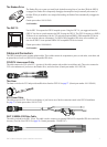
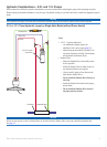
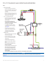
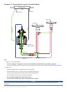
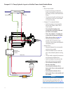
The Pump and the ECU
The cables from the pump to the ECU cannot be extended.
The pump must be located within 19 in. (0.5 m) of the ECU, and mounted horizontally if possible. If you cannot mount the pump
horizontally, do not mount the pump vertically with the pump head (connectors) down.
The ECU power cable connects to the boat battery.
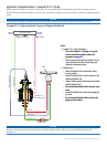
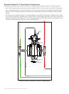
The CCU and the ECU
Mount the CCU in the forward half of the boat, no higher than 10 ft. (3.05 m) above the waterline.
Do not mount the CCU or the ECU in a location where they will be submerged or exposed to wash-down.
Do not mount the CCU near magnetic material, magnets (speakers and electric motors), or high-current wires. Mount the
CCU at least 24 in. (0.6 m) away from movable or changing magnetic disturbances such as anchors, anchor chain, wiper motors,
tool boxes, and the autopilot pump. Use a handheld compass to test for magnetic interference in the area.
You can mount the CCU below the waterline, if it is not in a location where it will be submerged or exposed to wash-down.
Mount the CCU bracket on a vertical surface or under a horizontal surface, so that the connected wires hang straight down.
The CCU/ECU interconnect cable connects the CCU to the ECU, and is 16 ft. (5 m) long. If you cannot mount the CCU within
16 ft. (5 m) of the ECU, replacement and extension cables are available. (See page 4).
The CCU/ECU interconnect cable connects the CCU to the Shadow Drive, the alarm buzzer, the tachometer of the boat, and the
yellow CCU signal wire of the GHC 10 using wires with bare ends. See page 26 for wiring instructions and diagrams.
If your boat uses an electrical system that provides more than 12 Vdc, or if you sporadically receive tachometer errors, install an
external tachometer lter (010-11399-00). Contact your local Garmin dealer or Garmin product support for more information.
The CCU and the GHC 10
The CCU and the GHC 10 connect to a NMEA 2000 network. If you do not have a NMEA 2000 network on your boat, the
equipment necessary to build one is provided. For instructions on setting up the NMEA 2000 network, see page 30.
You can connect an optional NMEA 2000-compatible GPS device to the NMEA 2000 network to use waypoint and route data with
the GHP 10.
The GHC 10
Connect the GHC 10 to a NMEA 2000 network.
Connect the yellow CCU signal wire from the GHC 10 data cable to the yellow CCU signal wire of the CCU/ECU interconnect
cable. Connect the black wire to CCU ground.
If you do not have an optional NMEA 2000-compatible GPS device, you can wire an optional NMEA 0183-compatible GPS
device to the data cable of the GHC 10 instead (see page 32).
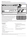
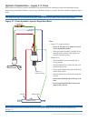
The Shadow Drive
Mount the Shadow Drive horizontally, as level as possible.
Mount the Shadow Drive at least 12 in. (0.3 m) away from magnetic material such as speakers and electric motors,
including the autopilot pump.
Install the Shadow Drive closer to the helm than to the pump.
•
•
•
•
•
•
•
•
•
•
•
•
•
•
•
•
•
•
•