


47GHP 10 Marine Autopilot System Installation Instructions
GHP 10 Installation Checklist
Detach this checklist from the installation instructions and use it to assist with the GHC 10 installation process.
Read all installation instructions before installing the GHC 10. Contact Garmin Product Support if you have any questions during the
installation process.
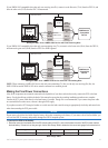
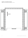
1. Refer to the charts on pages 9–18 for the proper locations of the pump, the Shadow Drive, and other hydraulic
requirements. Verify that the hydraulic steering layout of the boat supports the GHP 10 autopilot system.
2. Refer to the diagram and notes on page 5 to understand the necessary electrical and data connections.
3. Lay out all of the components, and check the cable lengths. Obtain extensions if necessary.
4. Mount the pump by following the directions starting on page 19. The pump must be located within 19
1
/
2
in. (0.5 m) of
the ECU.
5. Install the pump in the hydraulic steering system by following the directions starting on page 19. Do not bleed the
hydraulic steering system at this time (wait until step 14).
6. Mount the ECU by following the directions starting on page 25. The pump must be located within 19
1
/
2
in. (0.5 m) of
the ECU. Connect the pump to the ECU.
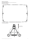
7. Mount the CCU by following the directions starting on page 25. Mount the CCU in a location free of magnetic
interference. Use a handheld compass to test for magnetic interference in the area. Mount the CCU in the bracket so
that the wires hang straight down.
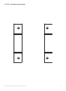
8. Install the Shadow Drive by following the directions starting on page 26. Do not bleed the hydraulic steering system at
this time (wait until step 14).
9. Wire the CCU to the tachometer of the boat by following the directions starting on page 27.
10. Mount the GHC 10 by following the directions starting on page 28.
11. Connect the GHC 10 and the CCU to a NMEA 2000 network. Connect an optional NMEA 2000-compatible GPS device
to the NMEA 2000 network (page 30).
12. Wire the yellow wire on the GHC 10 data cable to the yellow CCU signal wire on the CCU/ECU interconnect cable and
the black wire on the GHC 10 data cable to CCU ground. Wire an optional NMEA 0183-compatible GPS device to the
GHC 10 if a NMEA 2000-compatible GPS device is not available (page 29).
13. Complete the nal battery connections by following the directions on page 33.
14. Bleed the hydraulic steering system. Consult the manufacturer of your steering system for bleeding instructions.
Thoroughly check for leaks in the hydraulic steering system (page 34).
15. Apply a corrosion blocker to all of the installed components except the GHC 10. (Bo-Shield or Corrosion X,
for example)
16. Congure the GHP 10 system by completing the Dockside Wizard and the Sea Trial Wizard (page 35).
17. Re-examine the hydraulic steering system for leaks and for proper hydraulic uid levels.