


10
11
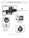
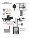
Pump Unit: This pump unit is designed for cylinder or cylinders equilivant to 10 - 25 cubic inches only.
The Pump unit will need to be mounted within at least 20” of the ECU. It will need to be mounted in a horizontal position
to a solid surface. Do not lengthen or splice the #5 wire or the orange and black power wires. Do not use this pump
with an unbalanced cylinder.
Deckmount: The deckmount should be mounted on the dash near the helm.
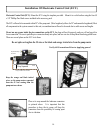
Electronic Control Unit (ECU): The ECU will need to be mounted within 20” of the pump unit. Most all components in
the system connect to this unit, so considerations will need to be made due to access and cable lengths. (Extension cables
are available.) Note: Make note of Serial #’s and record them in the Manual.
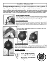
Compass Ball: The Compass Ball needs to be located in the forward 1/2 of the boat. Mount it in a location where it will
not be disturbed or damaged, and protected against wash down or submergence. Mount the Compass Ball no higher than
10’ above the waterline. The Compass may be extended using extensions available from TR-1. The Compass ball will need
to be accessed for the Warning Horn, GPS and Shadow Drive valve connections. When making those connections, use the
blue connectors provided in the accessory pack.
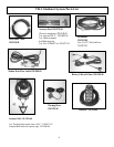
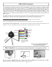
Tach Sensor Cables: You will need to splice the end of the tach sensor lead to the tach sensor wire from your motor. You
may need to refer to a wiring diagram of your motor. The other wire connects to a clean ground. The other end will plug into
the ECU at connection # 2 as per wiring diagram. The tach may be extended using shielded twisted pair wire.
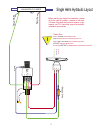
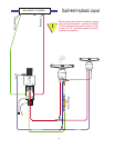
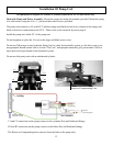
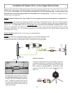
Shadow Drive Hydraulic Valve/Sensor: The Shadow Drive is an electronic bi-directional valve. It will need to be
mounted as shown in the system layout and can be extended using 18-22 gauge wire to make the electrical connections.
It needs to be mounted closer to the helm than to the pump unit, and will need to be mounted horizontally, and as level
as possible. (In a dual station helm, mount closer to and below the lowest helm.) Do not mount the Shadow Drive Valve
within 12” of any magnetic interference such as speakers or drive motors. Do Not Install
valve directly to the ttings
at the back of the helm. Be sure to install a length of hose between the tting at the helm and the Shadow Drive valve. TR-1
recommends a length of hose between Shadow Drive and any Tee. In a single helm installation, do not place a tee in the
line between the helm and Shadow Drive Valve. This is very important for the Shadow Drive feature to work correctly.
Air can and will get trapped in the valve during installation and bleeding. It’s very important to get all the air out of the
Hydraulic Lines, Helms, Pump, Cylinder (s) and The Shadow Drive valve.
Protection
Locate the Pump Unit, the ECU and the Compass Ball in a place where they will not be submerged or exposed to wash
down. Spray the installed components with a protective corrosion prohibitive like Bo-Shield or Corrosion X, etc.
Hydraulic Connections
Before starting the hydraulic installation, please verify the type of hydraulic steering in the boat. If it does not match the
hydraulic layouts in this manual, call technical support at 1-866-559-0229 for specic installation procedures. Examples
of steering systems that may need special instructions: Capilano, Hynautic, Latham.
Do not use Teon tape on any hydraulic ttings. However, for leak free hydraulic system, we do advise you to use an
appropriate thread sealant such as, Loctite “Pro Lock” multipurpose anaerobic gel, part number 51604, or equivalent on all
pipe threads.
It is TR-1’s recommendation to only use hose with machine crimped on ttings, or eld replaceable ttings that have
a minimum of 1,000 PSI rating.
Mounting Considerations, Protection, Hydraulic Connections, Magnetic
Environment, System Maintenance