


12
13
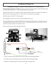
Installation Of Pump Unit
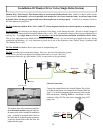
Hydraulic Pump and Motor Assembly: Mount the pump unit using the template provided. Mount the pump
to a solid surface using the #14 x 1” pan head sheet metal screws provided.
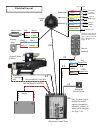
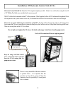
The pump unit connects to #5 at the ECU and the orange and black twisted wires connect to the orange and
black twisted wire connections at the ECU. Please refer to the electrical layout on page 8.
Install the pump unit within 20” of the pump unit.
Do not lengthen or splice the #5 wire or the orage and black power wires.
Do not use Teon tape on any hydraulic tting, but for a leak free hydraulic system, we do advise you to use
an appropriate thread sealant such as Loctite “Pro Lock” multipurpose anaerobic gell, part number 51604 or
equivalent on all pipe threads in the hydraulic system.
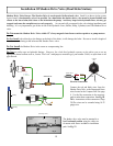
Do not use this pump unit with an unbalanced cylinder.
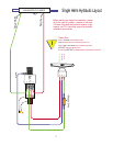
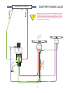
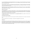
C1 and C2 connection on the pump connect to the cylinders Port and Starboard ttings.
H1 and H2 connection on the pump connect to the helms Port and Starboard ttings.
The Return or Compensating hose connects from the helm to the pump only.
C1
C2
H1
H2
Return or Compensating Line
This pump unit is designed for cylinder or cylinders equilivant to 10 - 25 cubic inches only.