


26
27
Section II
Dockside Setup and Sea Trial Setup of Autopilot
Your autopilot needs to be setup and tuned to your boat dynamics and motor conguration. It is important to get the
autopilot operating the best in can. The Dockside Setup and the Sea Trial Setup are steps that must be followed to achieve
the best performance from the TR-1 Gladiator Autopilot. Have patience and try to do the Sea Trial Setup on a nice calm
day. Follow the directions below. These steps are in a sequence to help keep you from making any errors. If you have
any questions, please call us at 1-866-559-0229.
Dockside Setup: Steps 1-9 can be done at the dock before heading for open water.
1.
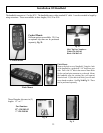
Turn autopilot system on
. Press the deckmount (on/off switch) on, the deckmount will blink slowly for 30 seconds during
startup. The system will automatically go into standby mode, and the deckmount will then blink rapidly. No functions are available
during startup. You will be using the handheld and deckmount switch to enter codes, change, and save the values of the parameters.
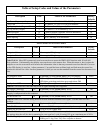
Parameters and their values are on the Table of Setup Codes, (Pages 35-37)
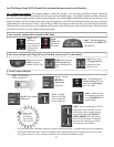
2
.
Lock to Lock times
. Count the number of turns it takes your helm to go from lock to lock and adjust the parameter of
code 26 to match. (Factory default is set at 4.5) The value of code 26 can be seen in the blink code ashed on the up
and down
arrow buttons on the handheld. Press and light up the [Setup] LED , press and light up numbers 2 & 6, [Code 26]. Press and hold the
[Select Load] (GPS) button. The number of turns is 1/10th of the blinked code + 1. Example: if the blinked code is 44 (The up arrow
will blink 4 and the down arrow will blink 4) the number of turns is (44 + 1)/10 = 4.5 turns lock to lock. To adjust the parameter, press
and light up the [Setup] LED , press and light up numbers 2 & 6, [Code 26]. Press the up and down arrows to adjust the parameter.
3.
Helm displacement
. The value of [Code 269] should be set to reect the helm displacement. (Factory Default is set at 1.7). Press
and release [Setup] button. Press and light up [Code 269] on the handheld. By pressing and holding down the [Select Load] (GPS) button
on the handheld, the up and down arrows will blink to reect the helm displacement code. The helm displacement is usually written on the
body of the helm pump. Example: The blinked code for a 1.7 cu in/rev helm would be 16, (the up arrow blinks once and the down arrow
blinks 6) since (16 +1)/10 = 1.7.
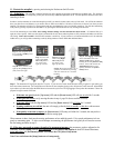
4. Verify the direction of steering is correct.
Turn the autopilot on and switch from standby to autopilot. When the right straight
arrow turn button is pressed on the handheld remote, the motor should turn the boat to the right. When the left straight arrow turn button is
pressed on the handheld/remote, the motor should turn the boat to the left. If this is incorrect use [Code 249] for reversed hoses. Press and
release, and light up the [Setup] LED, press and light up [Code 249] on handheld, if the down arrow is lit, press the up arrow to reverse
hoses. If you change this setting, download changes into permanent memory
by following step 8.
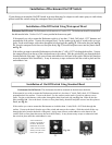
5. RPM Source Conguration.
The default setting on the autopilot is set for a Single Engine. If you have twin engines or more,
you will need to change [Code 259] to match your motor conguration. Twin engines; Press, release
and light up the [Setup] LED on
the handheld, press and enter [Code 259] on the handheld. Press the [Up Arrow] TWO (2) times which is setting the parameter to [(4)
Both]. See page 38 code 259 for more information.
6. Verify the autopilot tachometer (
Tach Sensor Cable
) is functioning properly
. With the engine(s) running. Press, release
and light up the [Setup] LED on the handheld, and press and light up [code 35]. Press and hold
the [Select Load] GPS button and you
should see the [Up Arrow] and [Down Arrow] LED’s blink your port engine’s RPM. For example, when the [Up Arrow] LED blinks
2 times and the [Down Arrow] LED blinks 5 times your engine is running at 2500 RPM. [Code 36] works the same way as code 35
for the starboard engine instead of the port engine. The autopilot tachometer system has a lower limit setting of 200 RPM. If needed,
adjusting [Code 267] (pulses per rev) to make your autopilot tachometer match the tach on your dashboard.
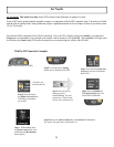
7.
Transition RPM.
This is the RPM at which your boat
transitions from displacement to planing speed. [Code 348] is set to a factory
default of 3000 (2 blinks of the [Up Arrow] LED and 9 blinks of the [Down Arrow] LED +1). You should set it to your boat’s transition
RPM. (Example: Say that your
planing speed is at 2500 RPM’s; With the [Setup] LED lit, press and light [code 348], since the factory
default is 3000 which is 2 blinks of the up arrow and 9 blinks of the down arrow (The value can be seen with the [Setup] LED lit, press and
hold the [Select Load] GPS , release the select load button, then click the down arrow 5 times; that will set your transition RPM’s at 2500.)
If you don’t know what the transition RPM is, you will need to do this as part of your Sea Trial Setup.
8.
Download to permanent memory
the parameters you have adjusted so far. (This must be done) With the [Setup]
LED lit, press and hold
the GPS [Select Load] button - the [load] LED should illuminate on the handheld, while still holding
down the [Select Load] button, press and release the [Deckmount], on/off button quickly, then release the [Select Load]
GPS button.
9. Verify NMEA Connections:
Verify that the NMEA connections for the GPS are functioning. Turn on the GPS.
With the Autopilot in [Standby], press and release [Setup] button on the handheld. Press and light up the number 4 and
the number 8 LED’s[ Code 48]. If the [up arrow] LED lights when you hold down the [Select Load] (GPS) button, the
autopilot does not acknowledge the validity of the GPS data.