


14
15
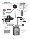
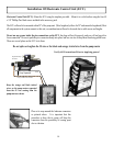
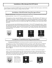
Electronic Control Unit (ECU): Mount the ECU using the template provided. Mount it to a solid surface using the four #8
x 5/8” Phillips Pan Head screws included in the accessory pack.
The ECU will need to be mounted within 20” of the pump unit. (Wire length only allows for 20” and cannot be lengthened) Most
all components in the system connect to this unit, so considerations will need to be made due to cable access and lengths.
Do not use any grease inside the pico connections on the ECU, the plugs will not t properly, and you will end up with a
loose connection. Be sure to push the pico connectors rmly into place, and use wire ties to keep them from being pulled loose.
There are several places on the ECU to tie them.
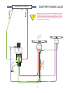
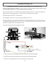
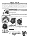
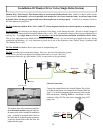
Keep the orange and black twisted
wires on the pump motor separated
from the #5 wire coming from the
pump motor as shown.
Do not splice or lengthen the #5 wire or the black and orange twisted wire from the pump motor
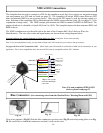
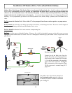
Place a tie wrap around the Anderson connectors
as pictured above. It is important that this
procedure is done; the tie wraps will keep the
connectors from the possibility of coming apart
due to vibration.
Keep Separated
Verify All Connections Prior to Applying power!
Installation Of Electronic Control Unit (ECU)
# 5
Orange and Black Twisted Wire
Hydraulic Pump
& Motor