


CHAPTER 3: ELECTRICAL INSTALLATION RELAY, PROTECTION AND PULSE OUTPUT
EPM 5300 SERIES ADVANCED POWER METERS – INSTRUCTION MANUAL 3–17
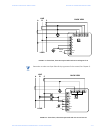
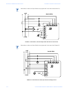
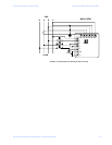
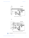
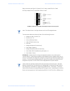
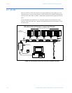
Relay connection (see Figure 3.6, below): Form C relays, rated 250V, 5A–2 each.
KYZ relay output (Form C), rated 200V, 100mA–1 each.
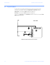
FIGURE 3–9: Close-up of the Relay and KYZ pulse output on the rear panel.
Note
Note: The relays shown in the figure above are in the NOT energized state.
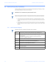
The instrument detects two levels of alarm for the following functions:
• Voltage: AN, BN, CN, AB, BC, CA
• Current: A, B, C, N
• Over and Reverse Power
• Under PF/KVAR Lead or Lag
•Over KVA
• Voltage Imbalance (One level only)
• Over/Under Frequency
• Voltage Phase Reversals (One level only)
• Over/Under %THD (Available only with option –H)
• Over/Under K-Factor
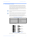
KYZ RELAYS: Provides pulses for energy management systems or any other type of
recording device. These pulses represent accumulated watt-hour, negative watt-hour, or
VA-hour. Accomplish this assignment through the Programming Mode (see programming
sections). The pulse value is determined by the decimal increment of the power function
assigned to the pulse. The EPM 5200P can be equipped with KYZ pulse outputs.
Note
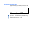
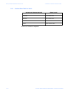
Unless otherwise specified, standard KYZ setup represents positive watt hour. See table
below for standard rate. The scale factor for wattage (KW or MW) and Full Scale Decimal
Point Placement is selectable in Programming Mode GROUP 1, FUNCTION 2. Follow the
Decimal Point Placement corresponding to the Change in Level. A multiplication or division
factor can be programmed. See Programming GROUP 0, FUNCTION 6 for a different rate.
20
21
22
23
24
25
26
27
28
N.O.
N.C.
COM
N.O.
N.C.
COM
K
Y
Z
A
LARM #1
A
LARM #2
PULSE
OUTPUT