


CHAPTER 12: GROUPS 4, 5 AND 6—SET LIMITS AND RELAYS GROUP 4: PROGRAMMING FORMAT FOR LIMIT CONDITION
EPM 5300 SERIES ADVANCED POWER METERS – INSTRUCTION MANUAL 12–93
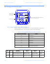
12.4 Group 4: Programming Format for Limit Condition
Note
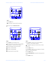
These functions have a two-part entry:
Part 1:
The first switch sets the limit to trip either above or below the Limit Value.
The second switch sets whether Relay 1 will trip when the condition occurs.
The third switch sets whether Relay 2 will trip when the condition occurs.
Part 2:
The second part is the Limit Value.
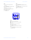
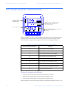
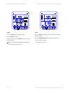
EXAMPLE: If voltages exceed 135 V, LM1 is triggered and Relay 1 is enabled. If the voltages
fall below 90 V, LM2 is triggered and Relay 2 is enabled.
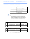
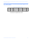
Table 12–1: Group 4 Programming Format
Group and Function Number Function
40. LM1/LM2 Set Limits for Volts AN, BN, CN
41. LM1/LM2 Set Limits for Volts AB, BC, CA
42. LM1/LM2 Set Limits for Amps A, B, C
43. LM1/LM2 Set Limits for Amps Neutral
4E. Exit Programming GROUP 4
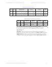
Table 12–2: Group 4: Functions 0–3
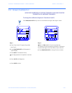
LM1
LED
LM2
LED
Above/below Relay 1 Relay 2 Value
ON OFF
Digit Up-trigger above value
Digit Down-trigger below value
Digit Up-enabled
Digit Down-disabled
Digit Up-enabled
Digit Down-disabled
0-9999
0-9999
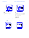
OFF ON
Digit Up-trigger above value
Digit Down-trigger below value
Digit Up-enabled
Digit Down-disabled
Digit Up-enabled
Digit Down-disabled
0-9999
0-9999
Table 12–3: Group 4: Example for Function 0
LM1
LED
LM2
LED
Above/below Relay 1 Relay 2 Value
ON OFF Digit Up Digit Up Digit Down 0135
OFF ON Digit Down Digit Down Digit Up 0090