


CHAPTER 4: COMMUNICATION INSTALLATION RS-485
EPM 5300 SERIES ADVANCED POWER METERS – INSTRUCTION MANUAL 4–25
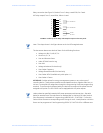
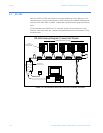
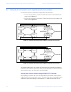
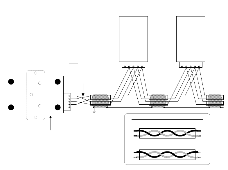
FIGURE 4–6: 4-Wire RS-485 Communication Connection Installation full duplex, detail view
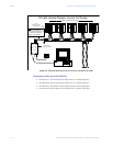
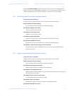
Connecting 4-Wire bus to RS-485 Port:
• Connect the T- wire of the Unicom 2500 to the R- on the RS-485 port
• Connect the R- wire of the Unicom 2500 to the T- on the RS-485 port
• Connect the T+ wire of the Unicom 2500 to the R+ on the RS-485 port
• Connect the R+ wire of the Unicom 2500 to the T+ on the RS-485 port
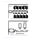
RS-485 Hookup Diagram (4 wire) Full Duplex: Detail View
GR+T+R-T- GR+T+R-T-
RS-485
Communications
Port
Model#
SF485DB
RS-485
Communications
Port
Model#
SF485DB
Gnd
R+
T+
R-
T-
UNICOM 2500
(Bottom View Shown)
RS-232
RS-485
T+ T-
T+T-
R-R+
R- R+
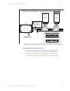
Receive Pair
Transmit Pair
Enlarged view of twisted pair segments
Note: This does not
represent a twisted pair.
It shows the cross-over
from R to T between the
Unicom and the rest of
the bus.