


CHAPTER 3: ELECTRICAL INSTALLATION CONNECTION TO THE MAIN POWER SUPPLY
EPM 5300 SERIES ADVANCED POWER METERS – INSTRUCTION MANUAL 3–9
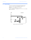
3.5 Connection to the Main Power Supply
The meter requires separate control power to operate. Listed are the five different power
supply options and corresponding suffixes.
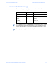
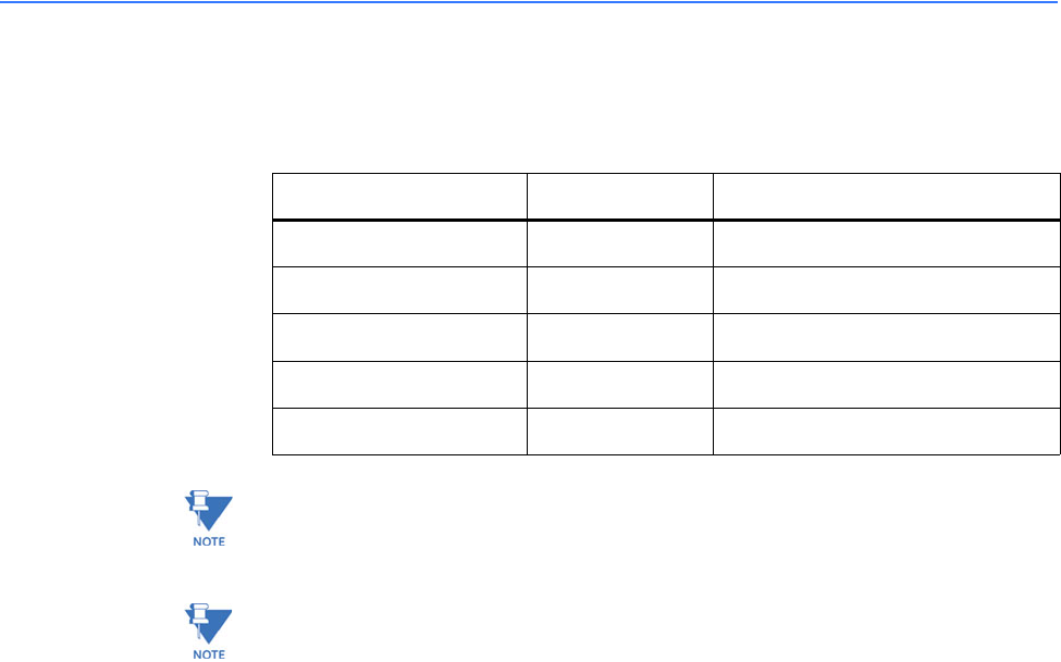
Table 3–2:
Control Power and Current
Note
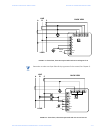
For DC-powered units, polarity should be observed. Connect the negative terminal to L and
positive terminal to L1. An earth ground connection to chassis is mandatory for normal
operation (terminal three). Do not ground the unit through the negative of the DC supply.
Note
Externally fuse power supply with a slow-blow 3 Amp fuse.
CONTROL POWER OPTION SUFFIX CURRENT
120V AC 115 A 0.1 AAC
240V AC 230 A 0.05 AAC
12V DC D4 0.10 ADC
24-48V DC D 0.25-0.5 ADC
125V AC/DC (universal) D2 0.10 AAC or DC