


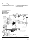
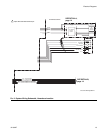
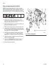

Electrical Diagrams
14 311594Z
F
IG
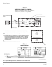
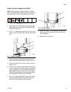
. 3: System Wiring Schematic, Hazardous Location Detail Views
8/(;3/26,213522)02725
-9$&8/
M
29(57(03
6:,7&+
02725-81&7,21%2;
/2:92/7$*(9
+,*+92/7$*(9
7
7
7
7
7
7
7
7
7
7
7
7
7
7
7
7
7
7
3
3
*51'
*51'
*1'
*1'
$7(;(;3/26,213522)02725
31-9$&
M
02725-81&7,21%2;
/2:92/7$*(9
+,*+92/7$*(9
*51</:*$$/3+$:,5(319(48,9
%/.*$$/3+$:,5(319(48,9
%/.*$$/3+$:,5(319(48,9
%/.*$$/3+$:,5(319(48,9
%/8*$07::,5(
%/8*$07::,5(
:
8
9
8
9
:
37&
8
9
:
:
8
9
6((6+((7
25
IS SENSOR
CIRCUIT
BOARD
(249639)
1
2
J2
1
2
3
4
5
TDC
NAMUR
SENSOR
(15H984)
J1
+ (BRN)
- (BLU)
(RED)
(GRN)
(WHT)
(BLK)
PRESSURE
TRANSDUCER
(120371)
3
4
J2
1
2
3
J3
BARRIER
(16A630)
ALL SWITCHES
"ON" POSITION 1
BARRIER
(16A633)
1
3
1
2
3
4
GREEN
RED
BLACK
FERRITE
(16G496)
BELDEN 8777 OR EQUIV.
WITH FERRITE (123375)
POSITION SENSOR
(16K088)
(16J588)
INSTALLED ON PUMP ASSEMBLY
INSTALLED IN E-FLO JUNCTION BOX ONLY
+(BRN)
-(BLU)
BLACK
5
2
DETAIL A
DETAIL B
$&7,9(%$55,(5
35(6685(75$16'8&(5&,5&8,7
8L 9
,L P$
3L :
&L X)
/L X+
1$085%$55,(5
7'&326,7,216(1625&,5&8,7
8L 9
,L P$
3L P:
&L Q)
/L X+
HAZARDOUS (CLASSIFIED) LOCATION
CLASS I, DIV. 1, GROUP C & D, T3 (FM ONLY)
GROUP II, CATEGORY 2 - ZONE 1, GAS (ATEX ONLY)
CLASS I, DIV. 1, GROUP C & D T3 (CANADA)
IS Control Drawing 288110
NON-HAZARDOUS
AREA
1 The installation must meet the requirements of the National Electric Code,
Canadian Electrical Code Part I, Article 504, NFPA 70, and ANSI/ISA 12.06.01.
Individually shielded cables needed to ensure separation of sensor and
transducer circuits.
The voltage (Vmax or Ui), current (Imax or Ii), and power (Pi) must be equal to or
greater than the voltage (Voc, Uo, or Vt), current (Isc, Io, or It), and power (Po or
Pt) levels, which can be delivered by the associated apparatus. In addition, the
maximum unprotected capacitance (Ci) and inductance (Li) of the intrinsically
safe apparatus, including interconnecting wiring, must be less than the
capacitance (Ca) and inductance (La) which can be safely connected to the
associated apparatus.
Land shield drain and foil to conductive strain relief.
2
3
5
SEE PAGE 13
3
HAZARDOUS AREA