


Repair
311594Z 35
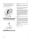
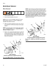
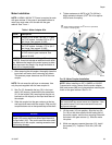
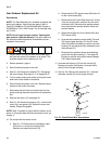
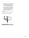
11. Install the two output seals (116) as follows:
a. Place tape over the output shaft keyway, to pre-
vent damage to the new seals. Pack the output
shaft seal cavity with Part No. 107411 Grease.
b. See F
IG
. 26. Push
one
output seal (116) onto
the output shaft (OS), with the lips facing in.
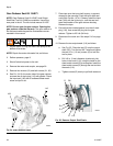
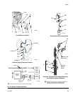
c. Remove the sheet metal screws from the tool
(C). Place the tool (C) onto the output shaft
(OS), fitting one screw (A) into the slot of the
shaft. Turn the tool 90°. Tighten the screws (G)
to lock it onto the shaft.
d. Place the installation tool (E) against the seal
(116) as shown.
e. Install the tool cover (F) and evenly tighten the
screws (J) to seat the seal on the output shaft
(OS).
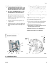
f. Remove the tools. Take three measurements
120° apart, from the surface of the seal to the
face of the housing (H). The three measure-
ments must be within .020 in. (0.5 mm). If not,
repeat steps c through e.
g. Repeat for the second seal (116). Remove the
tape.
12. Reconnect the crank arm. See steps 14-17 on page
27.
13. Reinstall the coupler and motor, see page 33.
14. Turn on electrical power to the unit.
15. Jog the motor to bring the lower on the side oppo-
site from the motor to the bottom of its stroke.
16. Shut off electrical power to the unit.
17. Repeat steps 9-12 to replace the output seals on
the side opposite from the motor.
18. Reinstall the covers (21, 32) and screws (12).
19. Add 2 quarts of gear oil, Part No. 288414.
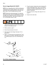
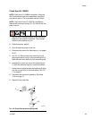
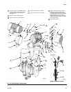
F
IG
. 26: Gear Reducer Seal Kit
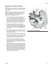
Pack cavity with grease before installing seal.
Insert until 109 contacts shoulder.
Insert until 116 contacts shoulder.
1
4
5
1
1
4
5
ti8682a
116
116
109
118
1
5
ti8963a
116
OS
ACEF
J
H