


Repair
311594Z 21
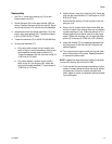
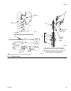
11. See F
IG
. 10. Loosen the nut (M) on the sensor con-
duit (44) and unscrew the adapter (42) from the
transducer port (P). Remove the transducer (25a)
from the port.
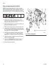
12. See F
IG
. 9. Loosen the nut (N) on the strain relief
(35). Remove the ferrite (76). Pull the transducer
cable (25a) out of the conduit (44).
13. See F
IG
. 10. Install one new black o-ring (41) and
the new brass spacer (58) on the transducer (25a).
14. See F
IG
. 9. Ensure that the conductive strain relief
(35) is screwed tightly into the housing, to ensure
electrical continuity to the pump housing. Thread
the transducer’s cable (25a) through the adapter
(42), short length of the conduit (44), and conductive
strain relief (35). Reconnect the cable to J1 on the
circuit board (25c). Install the ferrite (76) around the
transducer leadwires.
15. See F
IG
. 9. Tighten the nut (N) on the conductive
strain relief (35) securely to ensure that the shield
and drain wire (G) has firm metal-to-metal contact
between the nut and bushing (B).
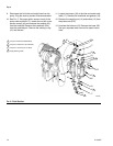
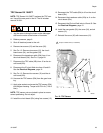
16. See F
IG
. 10. Insert the transducer into the trans-
ducer port (P). Torque the adapter (42) first, then
the nut (M) to 15-20 ft-lb (21-27 N•m).
17. See F
IG
. 9. Connect the TDC cable (25b) to J2 on
the circuit board (25c).
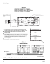
18. Ensure that the conductive strain relief (74a) is
screwed tightly into the housing. Units with a sensor
circuit must use the conductive strain relief to
ensure proper grounding of the IS field wire and
shield.
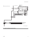
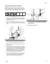
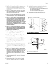
19. Thread the IS field wire and shield through the con-
ductive strain relief (74a) and connect it to J2 and
J3. See F
IG
. 11 and the Electrical Diagrams, page
12.
20. See F
IG
. 11. Tighten the nut (N) on the conductive
strain relief (74a) securely. Install the ferrite (77) on
the field wire (F), not more than 2 in. (51 mm) from
the bottom of the conductive strain relief (74a).
Install ground wire to grounding screw in junction
box.
21. Install the new gasket (33), the cover (34), and six
screws (12).
22. Remove the old label (L) from the circuit board
cover (34). Attach the new label (L) to the cover.
23. Calibrate the transducer, entering the calibration
information found on the new label (L):
• For systems using the Graco ACS Module, see
the ACS manual 3A0006.
• For non-ACS systems, see page 22.
24. Reinstall the cover (32) with two screws (12).
F
IG
. 10. Pressure Transducer
F
IG
. 11. IS Circuit Field Wire
44
42
41
25a
58
M
ti8721b
Torque to 15-20 ft-lb (21-27 N•m).
7
7
7
P
ti16891b
F
N
77
B
74a
Not more than
2 in. (51 mm)
G