


Repair
26 311594Z
Drive Section
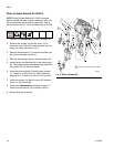
Slider Bearing Kit 15H882
NOTE: Slider Bearing Kit 15H882 includes parts to
rebuild both slider bearing assemblies. Use all the new
parts in the kit. The kit includes manual 311616.
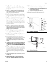
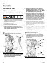
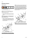
1. Jog the motor to bring the pump on the side being
repaired to the bottom of its stroke. This provides
access to the coupling nut (14).
2. Relieve pressure, page 9.
3. Shut off electrical power to the unit.
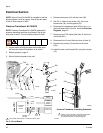
4. Remove two screws (12) and the cover. F
IG
. 14
shows the cover (32) on the side opposite from the
motor; the motor side cover is (21).
5. Place a clean rag over the top of the slider cylinder
(2) to prevent debris from falling into the slider
assembly during disassembly.
6. Remove the 2-piece shield (72) by inserting a
screwdriver straight into the slot, and using it as a
lever to release the tab. Repeat for all tabs. Do not
use the screwdriver to pry the shields apart.
7. Place a 3/4 in. wrench on the slider piston (9) flats
(just above the coupling nut), to keep the slider pis-
ton/connecting rod from turning when you are loos-
ening the coupling nut (14). Orient the wrench so it
is braced against one of the tie rods (3). Applying
excessive force to the slider piston/connecting rod
can shorten the life of the lower pin bearing.
8. Using a 1-5/8 in. open-end wrench, unscrew the
coupling nut (14) from the slider piston (9) and let it
slide down onto the pump piston rod. Be careful not
to lose the collars (13).
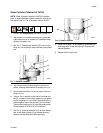
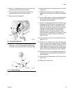
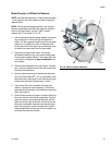
9. See F
IG
. 15. Using a 1/2 in. hex driver, unscrew the
two cap screws (5). Remove the crank arm cap (38)
and key (39). If necessary, use a plastic hammer to
break these parts loose.
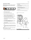
F
IG
. 14. Remove Coupling Nut
ti9223c
3
12
14
9
Place clean rag over slider cylinder (2).
Hold slider piston (9) flats with 3/4 in. wrench, and brace
against tie rod (3).
9
10
10
32
9
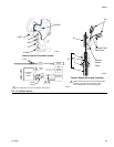
F
IG
. 15. Remove Crank Arm Cap
ti9224c
5
38
39
12
Place clean rag over slider cylinder (2).
Apply antiseize lubricant (LPS
®
-04110 or equivalent) to
screw (5) threads. Torque key-side screw to 210-230 ft-lb
(283-310 N•m) first, then torque gap side screw to 210-230
ft-lb (283-310 N•m). Torque screws an additional 2-3 times
each, or until they stop turning when torqued to 210-230
ft-lb (283-310 N•m).
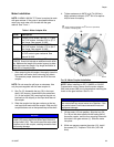
9
12
9
72