


Repair
20 311594Z
Electrical Section
NOTE: Sensor Circuit Kit 24J305 is available to add the
optional sensor circuit to a pump. Use all the new parts
in the kit. See manual 311603.
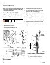
Pressure Transducer Kit 15H876
NOTE: Pressure Transducer Kit 15H876 replaces the
pressure transducer and the circuit board. Use all the
new parts in the kit. The kit includes manual 311600.
1. Jog the motor to bring the lower on the side oppo-
site from the motor to the bottom of its stroke.
2. Relieve pressure, page 9.
3. Shut off electrical power to the unit.
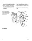
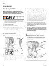
4. Remove two screws (12) and the cover (32).
5. See F
IG
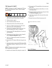
. 9. Remove six screws (12), the circuit
board cover (34), and the gasket (33).
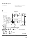
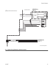
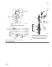
6. Disconnect the transducer cable (25a) from J1 on
the circuit board (25c). See F
IG
. 9 and the Electrical
Diagrams, page 12.
7. Disconnect the TDC cable (25b) from J2 on the cir-
cuit board (25c).
8. Disconnect the IS circuit field wire from J2 and J3.
9. Remove four screws (12) and the circuit board
(25c).
10. Install the new circuit board (25c) using four screws
(12).
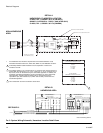
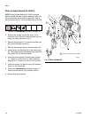
F
IG
. 9. Circuit Board
,66(1625
&,5&8,7
%2$5'
-
7'&
1$085
6(1625
-
%51
%/8
5('
*51
:+7
%/.
35(6685(
75$16'8&(5
-
-
)(55,7(
*
326,7,21
6(1625
-
%51
%/8
12
343325c
25b
ti8725b
25c
25b
25a
L
ti16890b
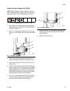
Pressure Transducer Grounding Schematic
76
25a
B
G
N
44
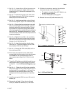
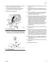
Tighten nut (N) securely to ensure that the shield
and drain wire (G) has firm metal-to-metal
contact between the nut and bushing (B).
3
3
35
ti17644a
ti17640a
76
35
35
74a*
Land shield drain and foil to conductive strain relief.
5