


Repair
36 311594Z
Gear Reducer Replacement Kit
Disassembly
NOTE: The Gear Reducer Kit is available to replace the
entire gear reducer. Use all the new parts in the kit.
Order Kit 15H886 for E-Flo 2000/3000/4000 Pumps or
Kit 289550 for E-Flo 1500 Pumps. The kit includes man-
ual 311615.
NOTE: Do not open the gear reducer. Opening the
gear reducer voids the warranty. The gear reducer is
not field serviceable beyond the maintenance recom-
mended in this manual.
1. Jog the motor to bring the lower on the side oppo-
site from the motor to the bottom of its stroke. This
provides access to the coupling nut (14).
2. Relieve pressure, page 9.
3. Shut off electrical power to the unit.
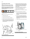
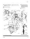
4. See F
IG
. 28. Remove the shields (72). Disconnect
the drive linkage. See steps 4-11 on pages 26-27.
5. Turn on power and jog the motor to bring the motor
side lower to the bottom of its stroke.
6. Shut off electrical power to the unit. Repeat the pro-
cedure for the motor side lower.
7. Disconnect the fluid inlet and outlet lines from the
pump and plug the ends to prevent fluid contamina-
tion.
8. Remove the motor (19), see page 30.
9. See F
IG
. 28. Remove the screws (12), circuit board
cover (34), and gasket (33). Retain the cover and
screws. Discard the gasket.
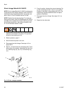
NOTE: Step 10 applies to pumps with the sensor circuit
option. If your pump does not have the sensor circuit, go
to step 11.
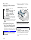
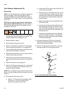
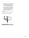
10. On pumps with the sensor circuit:
a. See F
IG
. 27. Disconnect the transducer cable
(25a) from J1 on the circuit board (25c).
Remove and retain the ferrite (76).
b. Disconnect the TDC sensor wires (25b) from J2
on the circuit board (25c).
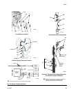
c. Disconnect the IS circuit field wires from J2 and
J3 on the circuit board, and from the two termi-
nal blocks (46). Disconnect the position sensor
wires from the two terminal blocks. Retain the
terminal blocks.
d. Remove and retain the circuit board (25c) and
TDC sensor (25b).
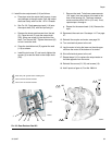
e. Unscrew the conductive strain reliefs (74a and
35) from the gear housing. Pull the 45° strain
relief (35) and the transducer conduit out of the
housing. Do not disconnect the transducer from
the outlet port (P).
f. Disconnect the position sensor and attaching
parts from the gear housing (1). See page 24.
Be sure to remove the position sensor adapter
(78). Retain these parts.
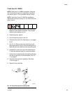
11. Unscrew the locknuts (15) from the tie rods (3).
Remove the entire fluid section. Unscrew the tie
rods (3) from the gear housing.
12. See F
IG
. 28. Remove the setscrew (31). Unscrew
the slider cylinder (2) from the gear reducer.
F
IG
. 27. Circuit Board Wire Connections
25c
25b
25a
ti17640a
76
35