


Repair
311594Z 33
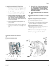
Motor Installation
NOTE: A NEMA 182/184 TC Frame is required to mate
with gear reducer. If the pump is purchased without a
motor you must order a kit to mate with the gear
reducer. See T
ABLE
1.
1. After removing the old coupler, thoroughly clean the
input shaft and motor shaft, removing any debris.
This ensures proper clearance and fit for the new
coupler.
NOTE: Do not reuse the old keys or setscrews. Use
only the parts supplied with the new coupler kit.
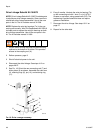
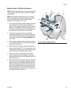
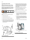
2. See F
IG
. 23. Assemble the key (20) in the input
shaft (105) keyway. Assemble the two setscrews
(31) in the coupler (28), ensuring that they do not
encroach on the keyway or the input shaft bore of
the coupler.
3. Slide the coupler into the gear reducer so the key
and input shaft mate with the coupler. Slide on until
coupler bottoms out on the tapered step of the shaft.
4. Tighten setscrews to 66-78 in-lb (7.4-8.8 N•m).
Apply antiseize lubricant (LPS
®
-04110 or equiva-
lent) to bore of coupling.
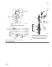
NOTE: When installing an IEC 112M/B5 or 100L/B5
Frame electric motor, ensure that the motor adapter
(MA) and screws (MS) are in place before mounting the
motor on the gear reducer. See F
IG
. 21.
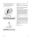
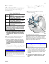
5. Lift the motor (19) into position. Align the key (36,
F
IG
. 28) on the motor shaft with the mating slot of
the motor coupler, and the four mounting holes with
the holes in the gear reducer (1). Slide the motor
into place.
6. While one person supports the motor (19), install
the screws (37). Torque to 75-80 ft-lb (102-108
N•m).
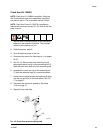
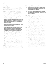
Table 1: Motor Adapter Kits
Kit No. Description
16C487 Coupler Kit for NEMA 182-184 TC Frame
3 or 5 HP motors. Includes 2.25 in. (57.2
mm) key★. See manual 311605.
15H880 Coupler Kit for NEMA 182/184 TC Frame
3 or 5 HP motors. Includes 1.75 in. (44.5
mm) key★. See manual 311605.
24E453 Mounts IEC 112M/B5 or 100L/B5 Frame 3
or 5 HP motor to gear reducer★. See
manual 311605.
★NOTE: All kits include the 0.62 in. (15.7 mm) key
(120376). Some kits include an additional motor shaft
key. Measure the length of the motor keyway to deter-
mine the correct key length. Key length should be at
least 90% of keyway length.
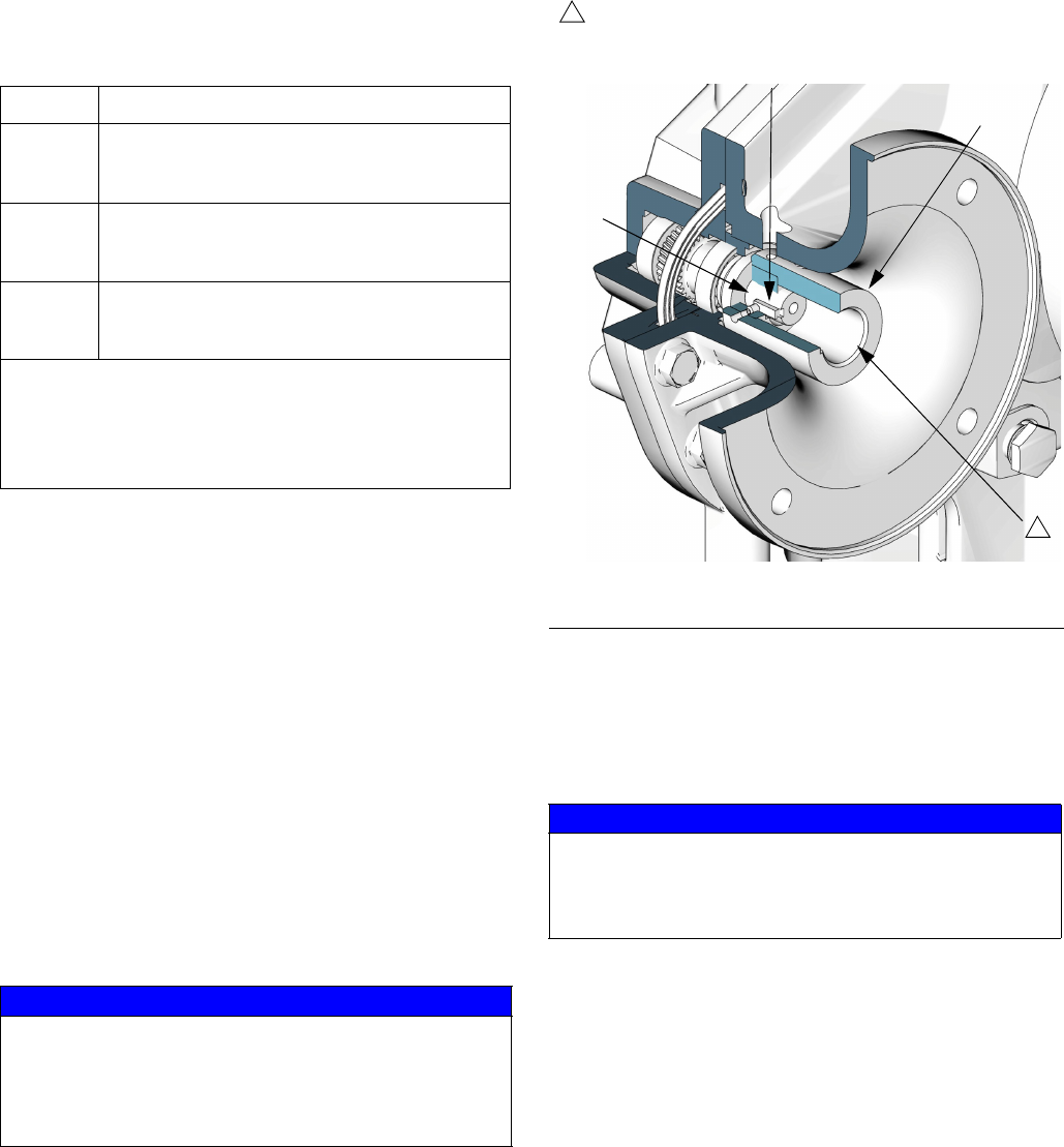
NOTICE
Ensure that neither the input key (20) or the end of the
coupler (28) motor shaft bore extend past the end of
the input shaft (105). This could cause the motor shaft
to bottom out on the coupler, causing excessive heat
and bearing damage.
F
IG
. 23. Motor Coupler Installation
NOTICE
When installing the electric motor, always ensure that
the motor shaft key cannot move out of position. If the
key works loose it could cause excessive heat and
equipment damage.
ti8913b
105
28
20
Apply antiseize lubricant (LPS
®
-04110 or equivalent)
to bore of coupling (28).
15
15