


Repair
34 311594Z
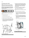
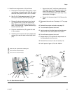
Gear Reducer Seal Kit 15H871
NOTE: Gear Reducer Seal Kit 15H871 and Output
Shaft Seal Tool Kit 15J926 are available. Use all the
new parts in the kit. The kits include manual 311597.
NOTE: Do not open the gear reducer. Opening the
gear reducer voids the warranty. The gear reducer is
not field serviceable beyond the maintenance recom-
mended in this manual.
1. Jog the motor to bring the motor-side pump to the
bottom of its stroke.
NOTE: Repair the motor side seals first, as follows.
2. Relieve pressure, page 9.
3. Shut off electrical power to the unit.
4. Remove the motor and coupler, see page 30.
5. Remove four screws (12) and both covers (21, 32).
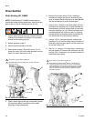
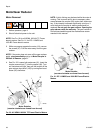
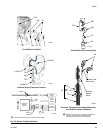
6. See F
IG
. 24. On the motor side of the gear reducer,
unscrew the oil drain plug (118) with gasket. Pierce
the input seal (109) with a hardened sheet metal
screw and pull it out.
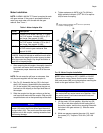
7. Place tape over the input shaft keyway, to prevent
damage to the new seal. Pack the input shaft seal
cavity with Part No. 107411 Grease. Install the input
seal (109) with the lip facing in, until the seal con-
tacts the shoulder of the gear reducer housing.
Remove the tape.
8. Ensure that the included gasket is on the oil drain
plug (118), then screw the plug into the gear
reducer. Tighten to 25 ft-lb (34 N•m).
9. Disconnect the crank arm. See steps 5-10 on page
26.
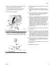
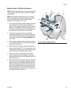
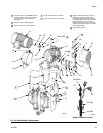
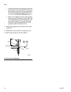
10. Remove the two output seals (116) as follows:
a. See F
IG
. 25. Place the tool (C) onto the output
shaft (OS). Turn the tool 90°. Install and tighten
the two 0.5 in. (13 mm) screws (G) to lock the
tool in place.
b. Drill 1/8 in. (3 mm) diameter (maximum) pilot
holes in the seals (116), using the holes for the
sheet metal screws (D) as a template. Install the
sheet metal screws (D) through the tool and into
the seals (116).
c. Tighten screws (D) evenly to pull both seals out.
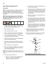
F
IG
. 24. Gear Reducer Seals
ti8682a
116
116
109
118
F
IG
. 25. Remove Output Shaft Seals
ti8964a
116
G
C
OSD
D
G
D