


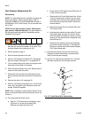

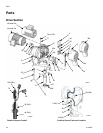
Repair
38 311594Z
Reassembly
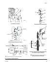
NOTE: Kit 15H886 includes a motor coupler (28),
already installed in the gear reducer. The coupler fits all
NEMA 182/184 TC Frame electric motors.
NOTE: To install an IEC 112M/B5 or 100L/B5 Frame
electric motor, order Motor Adapter Kit 15J893. See
T
ABLE
1 on page 33, and manual 311605.
1. Apply antiseize lubricant to bore of coupling.
2. Install the motor (19), see page 33.
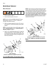
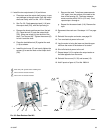
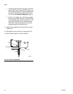
3. See F
IG
. 28. Screw the slider cylinders (2) into the
new gear reducer (1). Torque to 15-20 ft-lb (21-27
N•m). Install the setscrews (31). Torque to 30-35
in-lb (3.4-3.9 N•m).
4. Screw the tie rods (3) into the gear housing. Torque
to 50-60 ft-lb (68-80 N•m).
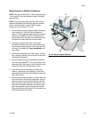
5. Orient the lowers (22) to the gear reducer (1) as
shown. Position the lowers on the tie rods (3).
Screw the tie rod locknuts (15) onto the tie rods.
Torque the locknuts to 50-60 ft-lb (68-80 N•m).
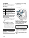
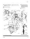
6. See F
IG
. 17 on page 27. Ensure that the joints
between the slider bearings (8) align with the pin
hole (PH) in the slider piston (9).
7. Reconnect the drive linkage. See steps 14-19 on
page 27.
8. Remove the rag from the slider cylinder.
9. Turn on power and jog the motor to bring the other
drive to the bottom of its stroke. Repeat procedure
to connect the other lower. Reinstall the shields
(72).
NOTE: Step 10 applies to pumps with the sensor circuit
option. If your pump does not have the sensor circuit, go
to step 11.
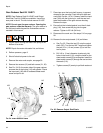
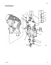
10. On pumps with the sensor circuit:
a. Remove the plug from the TDC sensor port at
the back of the circuit board cavity. Clean any
excess sealant from the area.
b. See F
IG
. 29. Apply pipe sealant and screw the
TDC sensor (25b) into the port. Torque to 66-78
in-lb (7.4-8.8 N•m).
NOTE: TDC sensor nuts are locked in place to ensure
correct positioning. Do not adjust.
c. Install the circuit board (25c) and four screws
(12).
d. Connect the TDC sensor (25b) to J2 on the cir-
cuit board (25c).
e. Install the position sensor and attaching parts in
the gear housing (1). See page 24.
NOTE: The Position Sensor nuts are locked in place to
ensure correct positioning. Do not adjust.
f. Ensure that the conductive strain relief (35) is
screwed tightly into the housing.
g. Connect the transducer’s cable to J1 on the cir-
cuit board (25c). Install the ferrite (76) around
the transducer leadwires.
h. Tighten the nut (N) on the conductive strain
relief (35) securely to ensure that the ground
wire (G) has firm metal-to-metal contact
between the nut and bushing (B).
i. Ensure that the conductive strain relief (74a) is
screwed tightly into the housing. Units with a
sensor circuit must use the conductive strain
relief to ensure proper grounding of the IS field
wire.