


is too short, extension cables are available to extend the transducer cable up
to a total of 50'. For assistance, contact the Customer Resource Center at
www.humminbird.com or call 1-800-633-1468 for more information.
NOTE: The transducer can pivot up to 90 degrees in the bracket. Allow enough
slack in the cable for this movement. It is best to route the cable to the side of
the transducer so the transducer will not damage the cable during movement.
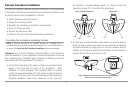
2a. If you are routing the cable over the transom of the boat, secure the
cable by attaching the cable clamp to the transom, drilling 9/64"
diameter holes for #8 x 5/8" wood screws, then skip directly to
procedure 5, Connecting the Cable.
or...
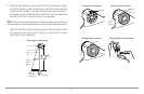
2b. If you will be routing the cable through a
hole in the transom, drill a 5/8"
diameter hole above the waterline.
Route the cable through this hole, then
fill the hole with marine-grade silicone
sealant and proceed to the next step
immediately.
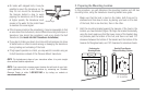
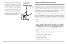
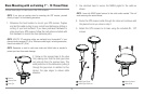
3. Place the escutcheon plate over the
cable hole and use it as a guide to mark
the two escutcheon plate mounting
holes. Remove the plate, drill two 9/64"
diameter x 5/8" deep holes, and then fill
both holes with marine-grade silicone
sealant. Place the escutcheon plate over
the cable hole and attach with two
#8 x 5/8" wood screws.
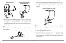
4. Route and secure the cable by attaching
the cable clamp to the transom; drill one
9/64" diameter x 5/8" deep hole, then fill
hole with marine-grade silicone sealant,
then attach the cable clamp using a #8 x
5/8" screw.
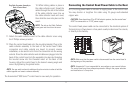
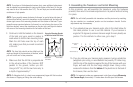
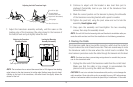
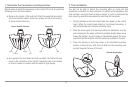
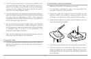
NOTE: If there is excess cable that needs to be gathered at one location (as
shown in the illustration), dress the cable routed from both directions so that a
single loop is left extending from the storage location. Doubling the cable up from
this point, form the cable into a coil. Storing excess cable using this method can
reduce electronic interference.
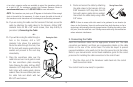
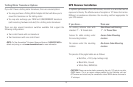
5. Connecting the Cable
Insert the transducer cable into the appropriate terminal slot. The cable
connectors are labeled, and there are corresponding labels on the cable
holder on the rear of the control head. The slots are keyed to prevent
reversed installation, so be careful not to force the connector into the holder.
Refer to your manual and/or control head installation guide for the correct
procedure for installing the cable connectors to the control head.
1. Plug the other end of the transducer cable back into the control
head connection holder.
Your control head is now ready for operation.
Storing Excess Cable
Routing the Cable
19