


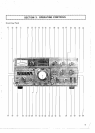
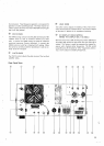

3.1
FRONT PANEL CONTROLS
@
METER
The meter monitors six different functions. depending on
the position of the METER switch. In receive the meter is
automatically an S-meter. The S-meter shows received si-
gnal strength on a scale of
0 to 40 db over S9. In transmit
the meter function depends on the position of the METER
switch. as described below.
@
METER SWITCH
The position of the METER switch determines the function
of the meter. The switch selects one of the following func-
tions (see Section 4 for nominal meter readings):
ALC
(Automatic Level Control)
-
In this position the
meter monitors the ALC voltage of the internal
ALC circuit (or the ALC voltage feedback from a
linear amplifier operated in conjunction with the
TS-820). For SSB operation the ALC reading for
voice peaks should be within the indicated ALC
range of
the meter. The ALC voltage adjustment
is made with the MIC control for
SSB and with
the CAR control for CW.
I
P (Plate Current)
-
In this position the meter moni-
tors the plate current of the final tubes. The me-
ter scale is calibrated from
0 to 350 ma.
RF:
(Output Power)
-
In this position the meter mo-
nitors the relative output power of the transcei-
ver. There is no meter scale for this position.
Normally the reading should be adjusted with the
RF VOLT control for a 2/3 scale meter reading,
T
COMP:
This indicates the state of compression when the
speech processor is operated.
HV:
(High Voltage)
-
In this position the meter moni-
tors the high voltage from the power supply. The
meter scale is calibrated from
0 to 10. indicating
0 to 1000 volts.
@
VFO INDICATOR
The VFO indicator is a
light emitting diode which illuminates
whenever the TS-820's internal VFO is controlling the trans-
ceiver's operation. The indicator is not lighted during fixed
channel. or remote VFO. operation.
This light emitting diode is illuminated when the RIT circuit
is turned on, showing that the transmit and receive frequen-
cies may be different.
@
SUB-DIAL
The sub-dial is turned with the main tuning knob to select
the operating frequency of the transceiver.
It is calibrated at
50 kHz intervals from 0
-
500 kHz.
@
DlAL SCALE
The unique mono-scale permits direct reading of frequencies
over the range of 0 to 500 kHz graduated at
1
kHz inter-
vals Operating frequency can be obtained by adding the
frequency read on the dial to the frequency
(MHz) indicated
on the BAND switch.
@
DlAL CALIBRATE KNOB
This knob is used to calibrate the reading on the dial scale.
It should not be used for tuning purposes.
@
MAIN TUNlG KNOB
Thls knob turns the VFO and dial scale to select the fre-
quency to be added to the band frequency to establish the
transceiver's
operating frequency.
@
STAND-BY SWITCH
This two position lever switch selects one of the following
functions:
REC: The transceiver is receiving unless the micro-
phone PTT switch is switched to transmit, or the
VOX circuit is activated.
@
ATT INDICATOR SEND: The TS-820 is'locked into the transmit mode in
this
swttch position.
Thls indicator uses a light emitting diode. It is illuminated
when the RF ATT switch is turned to ON.
@
FIX (FIXED CHANNEL OPERATION)
INDICATOR
The FIX
ind~cator is a lightemitting diode which illuminates
whenever the
TS-820's internal fixed frequency oscillator is
controlling the transceiver's operation.