


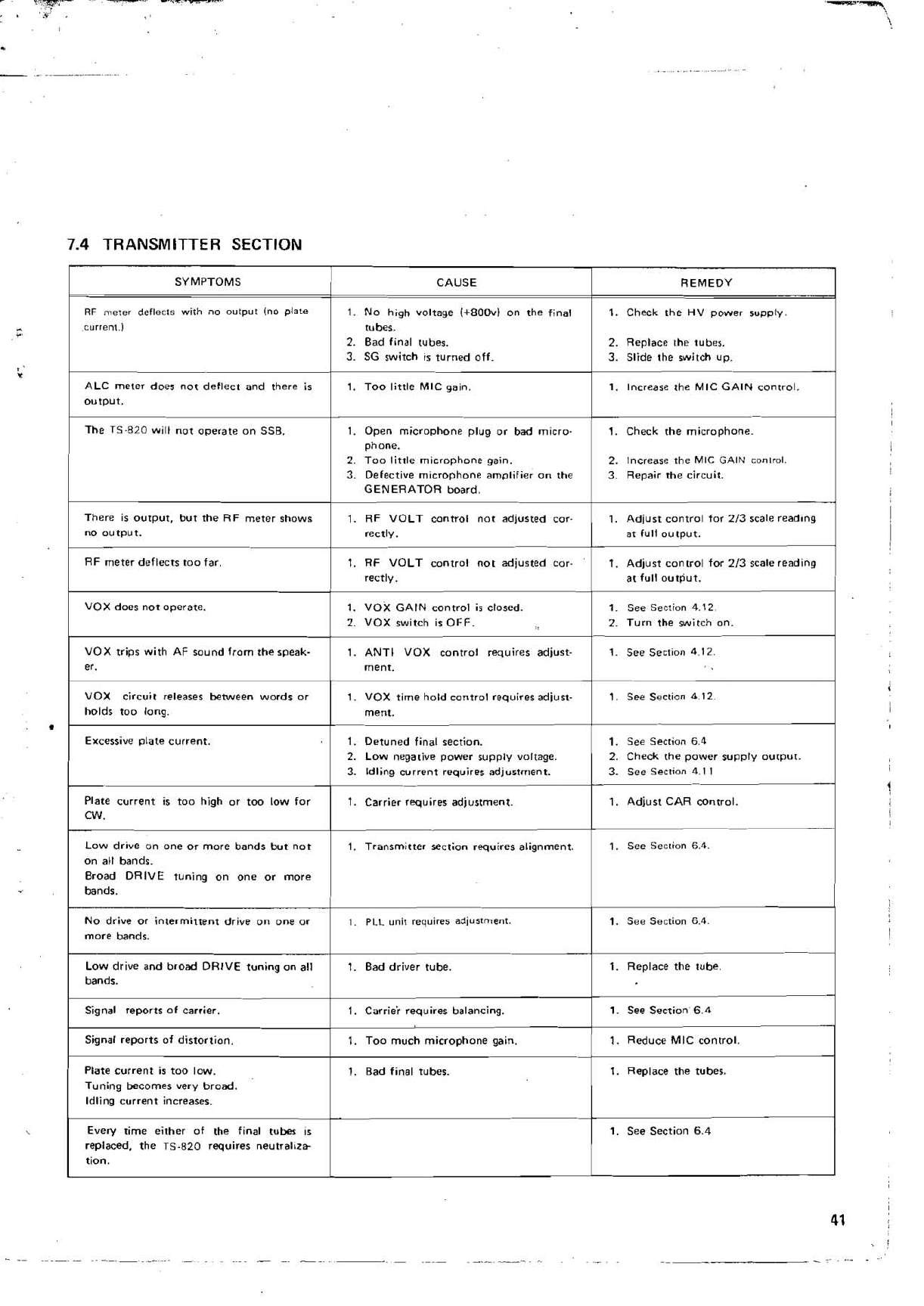
No
drive
or
intermittent drive
on
one
or
1.
PLL
unic requires adjustment.
1.
See Section 6.4.
more bandr.
7.4
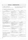
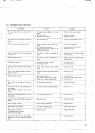
TRANSMITTER SECTION
-
+.
,
,
li
I
Signal reports of dirtortian.
1
1.
Too much microphone gain.
(
1.
Reduce MIC control.
I
Low drive and broad DRIVE tuning
on
all
bandr.
SYMPTOMS
RF
me~er
deflects with
no
outpur
In0
piale
current.]
ALC meter doer not deflect and there ir
output.
The
TS-820 will not ooerate
on
SSB,
There
is output, but the RF meter shows
no output.
RF meter deflects
too
far.
1.
Bad driver tube.
1.
Carriei requires balancing.
Plate current
is too low.
Tuning becomer very broad.
Idling current increaser.
Every rime either of the
final
tuber
is
replaced, the TS-820 requirer neutraltrb
tion.
!
1.
VOX GAIN control
is
closed.
1.
See Semion 4.12
2.
VOX switch is OFF.
2.
Turn the switch
on.
1.
Replace the tube.
1.
See
Section 6.4
requires alignment.
1.
See Section 6.4.
on
all bandr.
Broad DRIVE tuning
on
one
or
more
bandr.
1
!
i
CAUSE
1.
NO high voltage (+800v)
on
the final
tuber.
2.
Bad final tuber.
3.
SG rwirch is turned off.
1.
Too little MIC gain.
1.
Open microohone plug
or
bad micro.
phone.
2.
Too little microphone gain.
3.
Defective microphone am~lifier
on
the
GENERATOR board.
1.
RF VOLT control
not
adjusted
cor-
rectly.
1.
RF VOLT control
not
adjusted
cor-
rectly.
1.
Bad final rubes.
REMEDY
1.
Cheek the HV power supply.
2.
Replace the tuber.
3.
Slide the switch up.
1.
Increase the MIC GAIN control.
1.
Check the microphone.
2.
Increase
the MIC GAIN conlrol.
3.
Repair the circuit.
1.
Adiurt control
for
213
scale readong
ar
full output.
1.
Adjust control
for
213
scale reading
at full output.
1.
Replace the tuber.
1.
See Section 6.4
VOX
trips with AF round from the speak.
er.
1.
ANTI VOX control requires adjust-
ment.
VOX circuit
releaser between words
or
holds too long.
Excessive plate current.
Plate current is too high
or
too low for
1.
See Section 4.12.
1.
VOX time hold control requires adiurt-
ment.
1.
Detuned final recrion.
2.
Low negative power supply voltage.
3.
Idling current requires adjustment.
1.
Carrier requires adjustment.
1.
See Section 4.12.
1.
See Section 6.4
2.
Check the power rupoly ourput.
3.
See Section 4.1
I
-
1.
Adiurt CAR conrrol.