


~""'.""""""~.~,,,,,.,,,,,,.,,,,,>.#,,,,,.#,,,,.
.,,,,,
..*
888,
,.#
,888
,.#,,,,,.,,,,,..,
,,,,
,.,
,,,,
,.#
,,,,
,.,
,,,,
5
..,,,,,.
<
,,,,
,
.,,,,,
5
..................................................
,,,,
,
.,,,,,,.
#
,,,,
,.,,,,,,.#,,,,..,
,,,,
t.,,"$a.#,,,,8.,,,,,,.,,,
,,,.,,,,,,.,,,,,,.,
s,,,,.,",,,.,
,,,,
,
..,,,,
,
.,,,,,
,.,,,,,,,
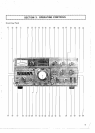
SECTION
1.
FEATURES
z
.,1111.111111.111,1,.,,,,,,.,,,,,,.#
,888
..,,,,,,.,,,,,,.,,,,,,.,,,,w.,,,,,,.,
,,,,
,.#,,,,,.,,,,,,.,
,,,,
,
.,,,,,
,.,
,,,,
,.,
,,,,..
,,,,a,.,
,,,,
,.#
,888
..#
,888
,.,,,,,,.,w,,,.,
,,,,
..,,,,,,.#,,,,,.,,,,Z,.,,,,,,.,
,,,,
..,
,,,,
,.#,,,,,.#,,,,,.<,,,,,
.,,,,,
,.,
,,,,
......................
....................
,
.,,,,,
.",,,,,.,,,,,.
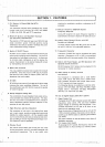
1. PLL System. HF Band SSB/CW/RTlY
Transceiver
checking the modulation condition or adjusting the
RF
processor.
This transceiver employs newly developed PLL (Phase
-
Locked Loop) circuit. covering 1.8 to 29.7 MHr (WWV
9.
Selector Switch for SSB/CW Receive
15
MHz) for SSB, CW and RTTY ooerations.
Frequency Response
-
2. Minimum Spurious and Excellent Overload
and Crossmod. Characteristic
-
.-
The adoption of FET baianced type mixer. MOS FET and
single conversion system minimizes spurious during
transmission and assures excellent overload and
cross-
mod. characteristic during reception.
3.
Built-in IF SHIFT Circuit
IF SHIFT circuit is built in the transceiver to shift IF pass
band without changing receive frequency. The circuit is
also called the "pass band tuning circuit". It allows you
to eiiminate radio interference or
sei the receive fre-
quency characteristic to the desired bandwidth simply
by manipulating one control knob.
4.
Built-in RF Processo~
The unique speech processor uses a quick time constant
at 455 kHz. Since this circuit is of RF type. it produces
little distortion and. unlike the clipper system, does not
deteriorate the tonal quality.
5.
RF NFB
RF NFB from the transmit final stage
tothe driver stage
improves the cross modulation distortion. The use of
the
ampl~fication type ALC further improves the quality
of transmit signals.
;
6.
Newly Designed Analog Dial
The combination of newly designed mono-scale and
su-
b-dial provides easy reading of frequencies. The adop-
1
tion of a circuit that is completely free from changes in
carrier frequencies permits accurate indication of fre-
quencies on one dial pointer.
7. Rigid Structure and Easy Operation
The transceiver is built with a die casting front panel
and a
rlgid chassis, providing outstanding mechanical
stability for mobile operation. All the operating parts
such as control knobs and dials are designed and arran-
ged according to human engineering technology to en-
sure maximum case of operation.
8.
Monitor Circuit
The monitor circuit allows you to hear your own voice
during transmission. which is normally impossible with
conventional transceivers. This
1s very useful when
During CW reception the audio frequency response is
automatically narrowed
to improve the clarity of sound.
10. Build-in Fixed Channel Circuits with RIT
(crystals are optional)
The
flxed channel circuits with RIT permit the use with
the built-in VFO for
more enjoyable operation.
11. Transverter Connector
Transverter
TV-502 (2m) can be connected for ready
operation. Changeover to HF or VHF is accomplished
automatically with
the power switch of the transverter.
12. Built-in AC Power Supply, and DC Operation with
Optional DC-DC Converter
DC-DC Converter DS-1
(optton) can be attached to the
transceiver for
mob~le operatlon
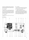
13. Wide Variety of Auxiliary Circuits
and Devices
The transceiver is completed with a noise blanker
circuit. VOX circuit, side tone circuit. marker circuit.
built-in speaker.
3-position AGC switch. healer switch.
IF OUT terminal and linear terminal.
The following devices are available as optional extra:
Remote VFO
(VFO-820). CW
Filter
(YG-88C). Digitai
Display
IDG-1). Transverter (TV-502). Microphone
(MC-50). Law Pass Filter (LF-30A).
14.
Use of Digital Display Dial DG-1 (option)
1)
Digital Display Dial
The digital dial of TS-820 indicates transmit and receive
frequencies using carrier. VFO and local oscillator
signals instead of converting VFO frequencies.
Thus.
accurate frequencies can be read at all times at any
band and any operating made.
Since the accuracy of frequencies is set up
anly
by
the
1 MHz standard oscillator, frequencies can be read ac-
curately up to 100
Hz
order by calibrating the 0S~illat0r
with WWV.
The green indication on the dial assures many hours Of
fatigueless operation.
2)
DH (display hold) Switch
By pressing the
DH switch. the frequency read on the
digital remains on, thus serving as a memory system.