


3.2
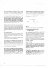
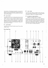
REAR PAN EL CONTROLS
a
RFVOLl
Use the RF VOLT control to adjust the
sensitivity
of the RF
output function of the meter Adjust it for a 2/3 scale rea-
ding during CW transmission.
@
COOLING FAN
This fan cools the RF amplifier section of the
TS~820 to In-
sure reliable and efficient operation.
ANTENNA CONNECTOR
This
50-239 coax connector should be attached to a suita-
ble antenna for transmitt~ng and receiving. See Section 2.4
for a discussion of an appropriate antenna.
@
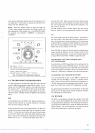
BlAS CONTROL
The
BlAS control adjusts the bias voltage of the two
S2001A 16146B) amplifier tubes. Tuning the control clock-
wise increases the idling plate current of the tubes. Section
4 describes adjustment of the bias current.
a
SG SWITCH
The SG slide switch controls the screen grid voltage on the
final tubes. For tuning or neutralizing the TS-820 you can
set the switch to the OFF position. Turn the switch back to
the ON position for normal operation. The SG voltage
1s on
when the switch is up and off when the switch is down.
8
TRANSVERTER IN JACK
This is the RF input jack for input from a VHF transverter.
*
-
a
TRANSVERTER OUT JACK
This is the low level RF output jack for use with a VHF trans-
verter.
GND
IGROUNDI LUG
Toprevent accidental shocks from the chassis. as well as in-
terference. connect a good earth ground to this lug.
FUSE
This fuse is a 3AG.
4
amp fuse which protects the power
supply of the transmitter against short circuits. Never use a
higher amperage fuse than the one specified. An improper
one can cause extensive damage to the transmitter. When
the fuse blows out. try to determine the cause before repla-
cing it.
Wnen the position of the AC Voltage Selector
Sw~tch is
changed. it is also necessary to change the power fuse. For
120 volt operation a 6 ampere fuse. for 220 volt operation a
4
ampere fuse prov~ded with the TS-820 should be used.
@
AC
VOLTAGE SELECT SWITCH
This
sldde switch switches the primary of the power transfor-
mer to select 120 or 220 VAC operation.
@
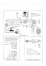
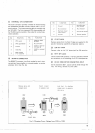
POWER SUPPLY CONNECTOR
This 12-pin connector is used to connect an AC or DC power
source to the transceiver.
@
TRANSVERTER CONNECTOR
This 12-pin connector is used to control an accessory VHF
transverter.
FUNCTION
+
FUNCTION
Tranrverter
in
Normally closed
relay
contact
Ground
10 +210
VDC
11
No
connection
12
Ground
'i
3
4
5
6
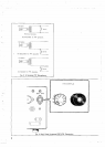
@
X
VERTER SWITCH
When VHF Transverter
JTV-502) is connected to the trans-
ceiver. the selection of HF or VHF is automatically accom-
plished by setting the transverter switch to ON or OFF.
t210
VDC
No
connectton
100
VDC
Tranrverter
in
@
PHONE PATCH IN JACK
This is a phone patch input terminal for transmission of
SSTV or other line inputs.
@
PHONE PATCH OUT JACK
This is a line output terminal for phone patch or recording. It
is also used for connection to the input of FSK demodulator
SSTV.
@
SPEAKER JACK
The receiver audio output can be connected through this
jack to the external 4 to 16 ohm speaker. The internal
speaker is disconnected when an external speaker is con.
nected.