


SECTION
2.
INSTALLATION
2.1
UNPACKING
ve. and between 15 and 200 ohms wfll take ~ower from the
Remove the TS-820 from its shipping box and packing
material and examine it for visible damage.
If the equipment
has been damaged in shipment. save the boxes and packing
material and notify the transportation company immedia-
tely. It is a good idea to save the boxes and packing material
in any case because they are very useful for shipping or mo-
ving the equipment.
transceiver with little difficulty.
If openwire or balanced type
transmission line is used with the antenna. a suitable an-
tenna tuner is recommended between the transceiver and
the feed
llne Methods of construction and operating such
tuners are
descr~bed in detail in the ARRL Antenna Hand-
book. and similar publications. For operation on 75 and 40
meter bands. a simple dipole antenna. cut to resorlance in
the most used portion of the bands. will perform
satisfacto-
5
rily For operation of the transceiver on the 10. 15. and 20
The following accessories should be included with the trans-
ceiver:
meter bands. the efficiency of the station will be greatly in-
creased if a sood directional
rotary antenna is used. Re-
1 Operating Manual
1 Microphone Plug
1 Jumpered 9-pin Plug
(~nstalled)
5 RCA Phono Plugs
1
Alignment Tool
2 Plastic
Extension Feet
with Screws
1
AC Power Cord
1
Speaker Plug
1
8P US Plug
4 Fuse
(6A
x
2. 4A
x
2)
2.2
OPERATION LOCATION
As with any solid state electronic equipment the TS-820
should be kept from extremes of heat and humidity.
Choose an operating location that is dry and cool, and avoid
operating the transceiver in direct sunlight. Also. allow at
least
3
inches clearance between the back of the equipment
and any object. This space allows an adequate air flow from
the ventilating fan to keep the transceiver cool.
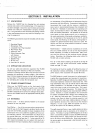
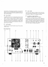
2.3
POWER CONNECTIONS
Make sure the POWER switch on the front panel of the
TS-820 is turned off, the stand-by switch is put in the REC
-
position. and that the voltage switch on the back of the
TS-820 is switched to the correct line voltage
(1 20 or 220).
Connect the POWER cord to an appropriate external power
source.
2.4
ANTENNA
Connect a 50
-
75 ohms antenna
feediine to the coaxial
connector on the rear panel.
Fixed Station
-
Any of the common antenna systems desi-
gned for use on the high frequency amateur bands may be
used with the
TS-820. provided the input impedance of the
transmission line is not outside the capability of the
PI-out-
put matching network.
The transmission line should be of
the coaxial cable type. An antenna system which shows a
standing wave ratio of less than 2
:
1
when using 50 or 75
ohm coaxial transmission line, or a system that results in a
transmission line input impedance that is essentially
resisti-
.
member that even the most powerful transceiver is useless
without a proper antenna.
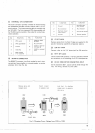
Mobile
Statlon
-
Mobile antenna installations are critical.
since any mobile antenna for use on the high frequency
bands represents a number of compromises. Many ama-
teurs lose the efficiency of their antenna through improper
tuning. Remember the following points when using the
TS-820 with a mobile antenna.
The
"Q"
of the antenna loading coil should be as high as
possible, There are several commercial models available
which use high
"0"
coils.
The loading coil must be capable of handling the power of
the transceiver without overheating.
In the CW mode the
power output of the transceiver will exceed 80 watts.
The SWR bridge is a useful instrument, but unfortunately it
is quite often misunderstood. and overrated in importance.
Easically. the SWR bridge will indicate how closely the an-
tenna load impedance matches the transmission line. With
long transmission lines. such as will be used in many fixed
station installations. it
isdesirable to keep the impedance
match fairly close in order to limit power loss. This is parti-
cularly true at the higher frequencies. The longer the
he.
and the higher the frequency, the more important SWR be-
comes However. in mobile installations the transmission
line seldom exceeds 20 feet in length, and an SWR of even
4 to 1 adds very little power loss. The only rime SWR will
indicate a low figure is when the antenna presents a load
close the 50 ohms, but-many mobile antennas will have a
base
nmpedance as low as 15 or 20 ohms at their resonant
frequency.
In such a case. SWR will indlcate
3
or
4
to 1.
and yet the system will be radiating efficiently.
The really important factor in your mobile antenna is that is
should be carefully tuned to resonance at the desired fre-
quency. The fallacy in using an SWR bridge lies in the fact
that it is sometimes possible to reduce the SWR reading by
detuning the antenna. Field strength may actually be redu-
ced in an effort to bring SWR down. Since field strength is
the primary goal, we recommend a field strength meter for
antenna tuning.