


6.3
ADJUSTMENT OF RECEIVER SECTION
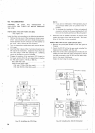
ADJUSTMENT OF 9V AVR VOLTAGE (AF-AVR UNITI
Adjust VR4 for
9V between the terminal "9" and chassis.
ADJUSTMENT OF AGC
BIAS (AF-AVR UNIT)
-
Adlust VR1 for 3 3V between the term~nal "RF1' and the
chass~s
RIT ADJUSTMENT (AF-AVR UNITI
Set the RIT knob to its center position and turn on the RIT
switch. Rotate the main tuning knob until the marker signal
can be heard
in suitable beat tone. Then. adjust VR2 so that
the beat tone is not varied regardless of the position of the
RIT switch.
MARKER FREQUENCY
CALIBRATION (MARKER
UNITI
The marker frequency is factory adjusted prior to shipment.
However, if it is deviated after a long period of use of the set.
it must be calibrated accurately. TS-820 is designed to re-
ceive WWV signals so that the marker frequency can be cali-
brated
prectsely.
Set the BAND switch on the front to WWV and turn the
main tuning knob until it is aligned with the
"0"
on the sub
dial. A standard 15 MHz WWV beat signal will be received.
By setting the FUNCTION switch to CAL-25 kHz, this beat
signal is superposed on the marker beat signal and is heard
as a double beat signal. Adjust the ceramic, trimmer
TC1 un-
til a zero beat is obtained. The marker frequency is now fully
calibrated.
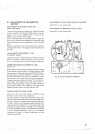
COUNTER FREQUENCY CALIBRATION
1
(COUNTER UNIT, OPTION)
*
With the FUNCTION switch in the VFO position. turn the
BAND switch to receive
15
MHz WWV standard signal. By
connecting the counter calibration cable suppled to the
counter unit and the X VERTER IN jack on the rear panel. the
WWV beat signal is superposed on the higher harmonics of
the standard signal of the counter and is heard as a double
beat signal. Adjust the trimmer of the counter unit to obtain
a zero beat. By so doing, the frequency indicated on the di-
gital display is accurately calibrated. After the calibration.
disconnect the counter calibration cable.
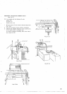
Set the FUNCTION switch to CAL-25 kHz to receive a
marker signal. Make certain
thattheANTterminalsareshorted
ted with a 50
-
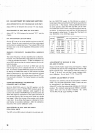
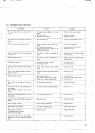
7551 resistor. With the DRIVE knob set to
its center position. adjust the ANT and MIX coils for maxi-
mum deflection of the S meter. using the frequency table gi-
ven below. In adjustment,
start with the
1
8 MHz band and
then proceed to other bands. To adjust the
10m band, use
only
29.0 MHz in the 29.0 MHz band.
Adjustment
1 1
I
I
1
Freouencv
ANT Coil MIX Coil DRIVE coil
/
2
1.8
1
1.90
MHZ
L8
1
L2
1
L15
1
3.5
7
14
ADJUSTMENT OF RECEIVE IF
COIL
(RF AND IF UNITS1
29.0
WWV
Receive 25 kHz marker signal using any frequency. Adjust
the DRIVE knob and the main tuning
khob for maximum def-
lection of the S meter. Then adjust
T2 of the RF unit and T4.
T5 and T7 of the IF unit until the S meter indicates maxi-
mum deflection. Do not touch TI. T2. T3 and 16.
3.75 MHz
7.15 MHz
14.175 MHz
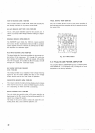
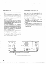
S METER ADJUSTMENT (IF UNITI
21
I
21.225 MHz L13
29.00 MHz
15.00
MHz
Disconnect the antenna and set the transceiver in receive
mode. The zero-point adjustment of the S meter can now
be acomplished in the following manner:
Adjust
VRl so that the meter pointer indicates its minimum
position.
If a standard signal generator (SSG) is available.
adjust
VR2 until the S meter indicates "9". using
14.175 MHz 40 dB signal (reading on
SSG)
L6 L19
LlO,
L1 1
L12
L14
L9 L 1
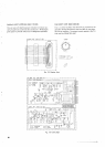
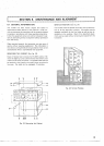
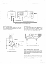
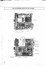
ADJUSTMENT OF ANT AND MIX COILS
(COIL PACK UNIT)
L16
1
L17
L5 L18
The ANT coil and MIX coil are included in the coil oack unit.