


SECTION
4.
OPERATING INSTRUCTIONS
. .
4.1
PRELIMINARY PROCEDURE
Set the MIC and CAR controls to zero and the MODE switch
to LSB.
USE. or CW to prevent acc~dental transmlt con-
d~tions before tunlng The TS-820 must be operated Into a
50
-
75
ohm antenna or dummy load w~th an SWR less
than 2 1. Random length
wlre antennas or light~bulb dum~
my loads cannot be used. Conventional half~wave d~poies
and bea~n antennas should only be used at or near tlwr
resonant frequency. Exceeding an SWR of 2
:
1 can
damage the components in the output stage of the
transceiver
Be
sure to complete all of the requlred cabl~ng. as described
in Section 2.3
-
2.8.
Wtth a su~table antenna and m~crophone (or key1 connected
to the
transcelver. set the TS-820 sw~tches to posltlonsdes-
crlbed
in
Table 1
4.2
RECEIVER TUNING
Refer to Table 1 for the ~n~t~ai sw~tch settlngs of the TS 820
for
recelvlng and then contlnue wlth the
described
proce
dure
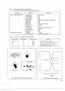
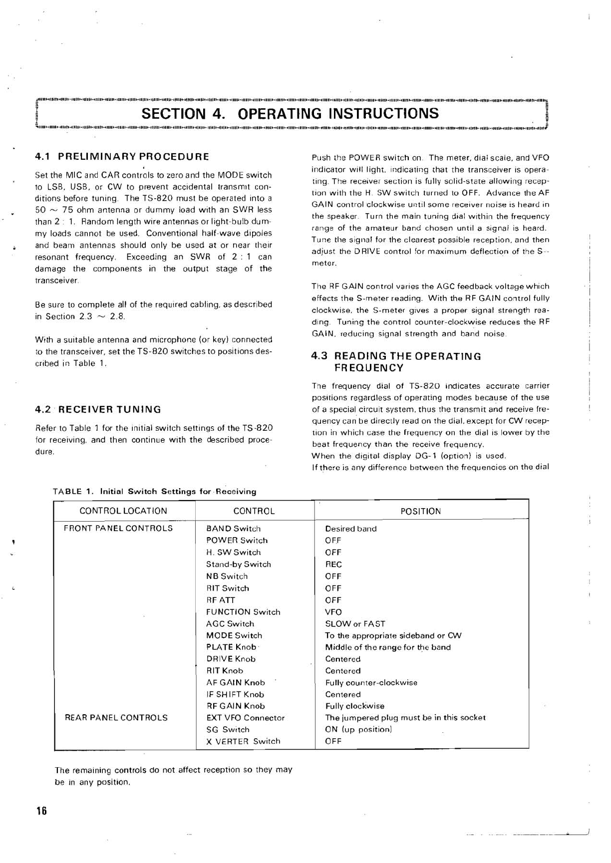
TABLE
1.
Initial Switch Settinqs
for
Receivinq
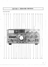
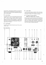
REAR PANEL CONTROLS
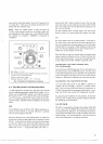
Push the POWER switch on The meter.
d~al scale. and VFO
ind~cator w~ll light. ~ndicating that the transceiver is
opera^
tlng The receiver section is fully solid-state allowing recep-
tlon with the
H
SW switch turned to OFF. Advance the AF
GAlN control clockwise
until
some recelver noise is heard
in
the speaker Turn the main tuning d~al w~tliin the frequency
range of the amateur band chosen
unt~l a signal is heard.
Tune
the signal for the clearest possible reception, and then
adjust the
DRIVE control for maximum deflection of the S--
meter.
The RF GAlN control
varles the AGC feedback voltage whlch
effects the S-meter reading. With the RF GAlN control fully
clockwise, the
S-meter glves a proper signal strength rea-
ding.
Tuning the control counter-clockwise reduces the RF
GAIN, reducing signal strength and band noise
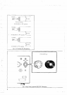
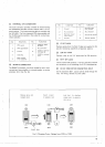
4.3
READING THE OPERATING
FREQUENCY
The frequency dial of TS-820 indicates accurate carrier
positions
regardless of operating modes because of the use
of a special circuit system. thus the transmit and receive fre-
quency can be directly read on the dial, except for CW recep-
t~on in which case the frequency on the dial is lower by the
beat frequency than the receive frequency.
When the
d~g~tal display DG-l ioptlon) is used.
If there is any difference between the frequencies on the dial
CONTROL
BAND Switch
POWER Switch
H. SW Switch
Stand-by Switch
NB Switch
RIT Switch
RF ATT
FUNCTION Switch
AGC Switch
MODE Switch
PLATE Knob
DRIVE Knob
RIT Knob
AF GAlN Knob
IFSHIFT Knob
RF GAlN Knob
EXT VFO Connector
SG
Swltch
X VERTER Switch
POSITION
Desired band
OFF
OFF
REC
OFF
OFF
OFF
VFO
SLOW or FAST
To the appropriate sideband or CW
Middle of the range for the band
Centered
Centered
Fully counter-clockwise
Centered
Fully clockwise
The
jumpered plug must be
in
this socket
ON
(up position1
OFF
The remaining controls do not affect reception so they may
be in any position.