


VOX-VR BOARD 1x54-1190-001
Three variable resistors. VOX GAIN. ANTI VOX and DELAY.
are directly mounted on a printed
circult board.
5V AVR BOARD (OPTION1
1x43-1220-001
Thts is a 5V power stab~l~zer used for the counter unlt It
uses IC to provlde rated voltage wlthout maklng any adjust-
ments
MARKER 80ARD 1x52-0005-011
The MARKER board holds the 100 kHz crystal oscillator
101) and a 25 kHz multivibrator 102 and 03) to produce
marker signals at 25 kHz intervals to calibrate the TS-820.
04 amplif~es the calibrator
signal^
RECTIFIER BOARD 1x43-1090-021
This board holds all of the diode rectillers for the power
sup^
ply section of the
transceiver.
Dl through D4 rectlly the
hlgh voltage. D5 rectifies the 300 volt supply.
D6
rectifies
the 210 volt supply. D7 rectifies the 90 volt supply. and
D8
through Dl 1 rectify the 13.8 VDC supply.
HV (HIGH VOLTAGE)
80ARD
1x43-1110-001
Thls voltage divider crrcuit s~lpplles a high voltage metering
s~gnal for the HV meter reading and also a low voltage
screen source used in the TUN mode of 'operation.
INDICATOR BOARD
1x54-1180-00)
Thls clrcult controls the light emitting diodes which indicate
1
when the RIT circuit is on, when the fixed frequency oscilla-
-
tor
IS
operating. or when the VFO is oscjllat~ng
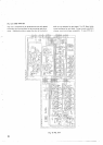
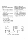
RELAY BOARD 1x43-1190-001
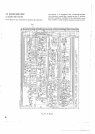
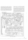
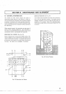
FINAL BOARD 1x56-12'00-00)
Th~s unit ~ncludes all the circuits of the power amplifier of
the
flnal stage wrth the exception of the pi~network clrcuit at
the output side.
Fig. 22 FINAL Board
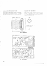
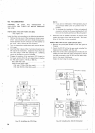
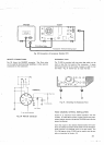
5.3
FINAL STAGE POWER AMPLIFIER
Thjs ampl~f~er deltvers 200W PEP tnput by 2 transmli power
tubes
(S2001A) It is equlpped w~th a cool~ng fan to
avoid
temperature rlse during operatton
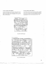
Th~s unit holds the stand-by relay. a 5V power
stabilizer
to
feed power to the PLL circuit. and
smoothing
capacitors to
obtain low voltage DC power.
The relay of
thls unit 1s used to select OC signal for con-
trolling block
b~as, cross channel operation. etc