


TABLE
3.
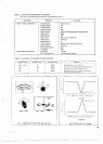
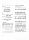
Summery of Transmitter Tuning Procedures
Table
2.
Initial Switch Settings for Transmission
(The controls not described should be set as described in Table
1)
MODE
Swtch
Procedure
Adlust BIAS
control
for
60
ma
TUN ALC SEND
Peak
the
ALC readlog
wlrh the
DRIVE
control
TUN
1
IP
1
SNED D8p
plate
current
~8th
PLATE conrrol
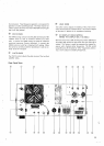
FRONT PANEL CONTROLS
REAR PANEL CONTROLS
~~a~d~~y~~~~~h~ BAND Switch Desired band
H.
SW Switch
MODE Switch USB or
LSB
depending on selected band
VOX Switch
MONl Switch
MIC Control Fully
counter-clockwise
CAR Control Centered
METER Switch
PLATE Control
Mlddle of the range for the band
DRIVE Control Centered
FUNCTION
Swltch VFO
RIT Switch
SG Switch UP
(ON)
EXT VFO Connector Jurnpered OFF plug ~nserted
METE
RF
5
8
80
2"
COUP
0
.LLC
'-a"
.e
CW
I
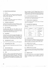
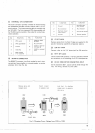
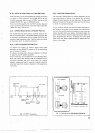
Fig.
7
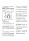
Adjustment of the Plate Idling Current
1
DRIVE adjosl~nenl
arigular
dspacemailt
(b)
ALC
RF
Fig.
8
Plate and Drive Tuning
19
SEND
Peak RF output
by
alternalely
adjusting
the
PLATE AND LOAD controls.