


[he RIT circuit is ON. By turning the RIT knob, the receive
frequency of VFO can be changed by
-1-3
kHz and the fre-
quency of fixed
channel by
-1-
150 Hz without changing the
transmit frequency.
@
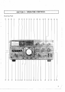
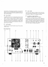
BAND SWITCH
This 1 1-position switch selects all the necessary circuits to
tune the transceiver to the desired 500 kHz band.
@
FUNCTION SWITCH
This 7-position rotary switch selects one of the following
Iransceive functions.
CAL-
This position allows
callbration of the TS-820's
FIX.
internal VFO to one of the transceiver's fixed fre-
quency channels (if an optional fixed channel cry-
stal is installed). With the switch in this position a
signal is generated at the selected fixed channel
frequency and the main tuning knob can be tuned
to zero beat the calibrating signal.
CAL-
This position allows calibration of the VFO-820
RMT:
(remote VFO) to the transceiver's operating fre-
quency. With the switch in this position. the
transceiver generates a
calibrat~ng signal and the
VFO-820 can be tuned to zero-beat the calibra-
ting signal.
CAL- With the switch in this position. the transceiver's
25 kHz: calibrator circuit generates a marker signal at
every 25
kHz for normal calibration of the internal
VFO.
VFO: The switch is kept in this position for normal
transceive operation.
VFOR: With the switch in this position, the
TS-820's in-
ternal VFO controls the receive function and the
internal fixed channel oscillator controls the trans-
mit function
(if fixed channel crystals are installed
in the oscillator)
FIXR: With the switch in this position. the
TS-820's in-
ternal VFO controls the transmit function and the
built~in fixed channel oscillator controls the re-
ceive function
(if fixed channel crystals are instal-
led in the oscillator). The VFOR and
FIXR allow
cross-channel operation without an external VFO.
FIX
Wlth the swltch in this pos~tion. the TS-820's
f~xed channel
oscillator
controls the transmit and
recelve function of the transceiver (if accessory
f~xed channel crystals are installed in the transcei-
ver).
@!
H. SW (HEATER) SWITCH
This switch turns
the heater circuits of the three transmitting
tubes on and off. The heaters would normally be turned to
OFF to reduce power
consumption in mobile or portable re-
ceiving.
@
POWER SWITCH
The POWER switch turns all the power on and off in the
TS-820.
@
RIT KNOB
Th~s knob
1s
used to change recelve
frequency
when the RIT
clrcujt is
in
operatlon Set the center posltlon (0) of the
RIT knob to the RIT OFF
@
IF SHIFT KNOB
By using this knob during reception. the center frequency of
the IF crystal filter can be shifted by
i1.7 kHz. facilitating
the adjustment of the tonal quality of receive signal or
elimi-
natlng radio interference from nearby frequencies. For nor-
mal operation. this knob should be set to the center position
(click is heard).
MIC GAlN KNOB
This
knob is used for adlustment of the galn of MIC ampltfler
dur~ng
SSB
operatton Adlust so that the meter polnter does
not deflect beyond the ALC zone
@
CAR (CARRIER) LEVEL KNOB
Used to adjust carrier level during CW operation. Adjust so
that the meter does not deflect beyond the ALC zone.
@
AF GAlN KNOB
This knob adjusts the gain of the receiving audio amplifier.
The audio volume of the received signal increases as the
control is turned clockwise.
@
RF GAlN KNOB
This control adjusts the gain of the receiver section's RF am-
plifier. Turn the knob fully clockwise for maximum gain and
for a correct S-meter reading. Turn the control counter-.
clockwise to reduce the gain.
@
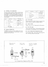
FIX CH (FIXED CHANNEL) SELECT SWITCH
Th~s four-position rotary switch selects between four diffe-
rent fixed frequency channels which can be installed inside