


The crystal frequency is determined by the following formu-
4.17 MOBILE OPERATION
las.
The compact size and solid-state design of the TS-820 make
it
deal for mobile use, by using optional DS-1.
Cgystal Frequency (MHz)
=
5.5 MHz
+
X
-
Operating Fre-
Be sure to use a mobile antenna which meets the require-
quency [MHz)
ments described in Section 2.
X
-
1.8 for the 160 meter band
X
=
3.5 for the 80 meter band
X
=
7.0 for the 40 meter band
X
=
14.0 for the 20 meter band
X
=
21.0 for the 15 meter band
X
=
28.0 for the 10 meter band or
X
=
28.5 for the 10 meter band or
X
=
29.0 for the 10 meter band or
X
=
29.5 for the 10 meter band
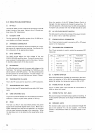
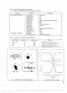
Crystal Specifications:
HC-25/U holder. 5.0 to 5.5 MHz os-
cillation frequency. and see Figure 9 for type of oscillation
circuit.
Example: Desired Operating Frequency
=
7.255 MHz
Crystal Frequency
=
5.5 MHz
+
7.0 MHz
-
7.255 MHz
=
5.245 MHz
This same crystal will operate on each band.
Operating Frequency
=
5.5 MHz
+
X (in MHz)
-
Crystal Frequency (in MHz)
Example: Crystal Frequency
=
5.245 MHz
On the 14 MHz band the crystal will oscillate at
Operating Frequency
=
5.5 MHz
+
14.0
-
5.245 MHz
=
14.255 MHz
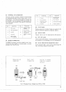
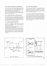
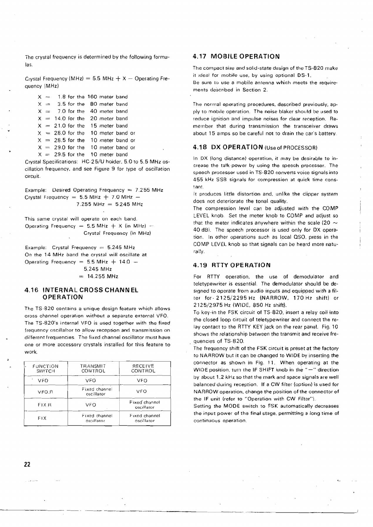
4.16 INTERNAL CROSS CHANNEL
OPERATION
The TS-820 contalns a unlque design feature which allows
cross channel operation without a separate external VFO.
The TS-820's internal VFO is used together with the fixed
frequency
osc~llaltor to allow
reception
and transmission on
different
frequencles.
he
fixed channel oscillator must have
one or more accessory crystals installed for
this
feature to
work.
FUNCTION TRANSMIT
1
Fixed
channel
1
VFOR
I
01cl1aIor
Fixed
channel
Fixed
channel
I
The normal operating procedures. described previously, ap-
ply
ro mobjle operation. The noise blaker should be used to
reduce ignition and impulse noises for clear reception. Re-
member that during transmission the transceiver draws
about 15 amps so be careful not to drain the car's battery.
4.1
8
DX
OPERATION
(Use of PROCESSOR)
In DX (long distance) operation, it may be desirable to in-
crease the
talk~power by using the speech processor. The
speech processor used in TS-820 converts voice signals into
455 kHz SSB signals for compression at quick time cons-
tant.
It
produces little distortion and, unlike the clipper system
does not deteriorate the tonal quality.
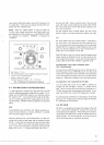
The compression level can be adjusted with the COMP
LEVEL knob Set the meter knob to COMP and adjust so
that the meter indicates anywhere within the scale (20
-
40 dB). The speech processor is used only for DX opera-
tion.
In other operations such as local QSO, press in the
COMP LEVEL knob so that signals can be heard more natu-
rally.
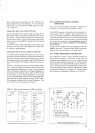
4.19 RTTY OPERATION
For RTTY operation, the use of demodulator and
teletypewriter is essential The demodulator should be de-
signed to operate from audio inputs and equipped with a fil-
ter for-
2125/2295 Hz (NARROW. 170 Hz shift) or
2125/2975 Hz (WIDE. 850 Hz shift).
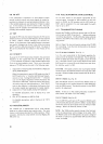
To key-in the FSK circuit of
TS~820. insert a relay coil into
the closed loop
c~rcuit of teletypewriter and connect the re-
lay contact to the RTTY KEY jack on the rear panel. Fig. 10
shows the
relat~onship between the transmit and receive fre-
quenc~es of TS-820.
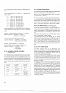
The frequency shift of the FSK
clrcuit is preset at the factory
to NARROW but it can bechanged to
WlDE by inserting the
connector as shown in Fig. 11. When operating at the
WlDE posirion, turn the IF SHIFT knob in the
"-"
direction
by about
1.2 kHz so that the mark and space signalsare well
balanced during reception.
If a CW filter (option) is used for
NARROW operation. change the position of the connector of
the IF unit (refer to "Operation with CW Filter").
Setting the MODE switch to FSK automatically decreases
the input power of the final stage, permitting a long time of
continuous
operation.