


15
Measurement µ
µµ
µs
A point in the signal transmitted, where the flow measurement is taken from. It is used to see if the signal is being taken
from the burst at the correct time to get the strongest signal. It is normally used on smaller pipes when the instrument is
being used in double or triple bounce as
signals can sometimes interfere with each other. This value is normally a few
µ
s below the
Up
µ
µµ
µ
s, Dn
µ
µµ
µ
s
value.
Phase up/dn µ
µµ
µs
Only valid if
Calculated
µ
µµ
µ
s
and
Up
µ
µµ
µ
s, Dn
µ
µµ
µ
s
are correct. If the reading is zero then there is no signal, which could
mean the pipe is empty, or the liquid is contaminated with particles or air.
Phase offset
This value will be between 0 and 15. The exact value is not important and will vary between applications. It should
however, be stable when the flow condition is good and velocity is within the range of the transducers being used. As
the flow rate increases towards and beyond the maximum, this figure will continuously change. In flow mode the
instrument will read unstable or high flow.
Flow (m/s)
This displays flow velocity in m/sec to 3 decimal places.
Signal
This is the average value of
Signal up/dn
and is a value between 800 and 2400 which
Display’s the signal strength as a percentage (800=0%, 2400=86%).
Signal up/dn
This value is internal to the electronics and must be greater than 800. There is an option in the
SET UP
INSTRUMENT
menu to allow this value to be taken down to 400 in extreme circumstances and is useful on some
applications when the signal levels are poor.
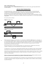
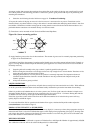
Sensor separation
This is a reminder for the user to check for correct sensor separation and sensor mode.
STATUS/ERROR/WARNING MESSAGES
There are three types of message that will appear and they are Status, Error and Warning. These messages appear under
the time and date on the display when in flow mode.
Status Messages
S1: INITIALISING
Appears when first entering flow mode to show instrument is starting up.
Error Messages
E1: UNSTABLE OR HIGH FLOW
This error message occurs when either the sensors have been positioned too near to an obstruction or bend causing
turbulence, or the instrument is being used outside its normal flow range.
When the instrument is programmed the user is informed of the maximum flow rate that is possible to measure and if
this is exceeded then the high flow message occurs.
It may be possible to get round these problems by moving the sensors to a straighter length of pipe or in the case of high
flows another set of transducers may be used.
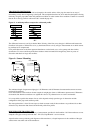
E2: NO FLOW SIGNAL
This message appears when the two transducers cannot send or receive signals, which could happen for various reasons.
Firstly check that all cables are connected, transducers are on the pipe correctly with grease on the face.
No flow signal will show if the pipe is empty or partially filled. When the liquid is aerated or when the particulate
content of that liquid is too high or if the grease has not been applied to the transducers and the condition of the pipe
being measured is poor.