


5
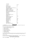
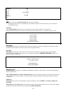
Figure 5:- Battery mains charger.
Is supplied with additional plug heads for use Worldwide. The charger is rated
90Vac to 265Vac 47/63mhz @1.1A
Battery Circuit
A battery management circuit controls the battery recharge. The circuit helps to prevent the batteries from being
damaged through overcharging. The circuit automatically cuts off the high-level charge current after 4hrs, after which it
will provide only a trickle charge. In operating mode a fully charged battery can maintain functionality for up to 8hrs
depending upon the demand. A large percentage of the demand taken by the ‘Backlighting’ and whilst it is continuously
enabled the operating life will drop to 4hrs from a fully charged battery.
When in flow measurement mode the battery charge level is continually displayed as a percentage of full charge. When
this indication reads approximately 40%, a warning message will appear on the screen. This indicates that there is only
30 minutes use left in the battery. The battery can be charged when the instrument is switched to the ON or OFF state.
See full instructions on charging and discharging the batteries on page 30-31.
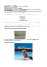
Keypad
Programming is via a key tactile membrane keypad.
When measuring flow it is possible, by selecting keys 4, 7, 8, and 9, to change from one unit to another without the
need to re-program. Additional key presses will adjust the time scale of the measurements.
Example:
•
Press 4 for m/s, press 4 again for f/s
•
Press 7 for l/s, press 7 again for l/min
•
Press 8 for g/min, press 8 again for USG/min
•
Press 9 for m
3
/hr, press 9 again for m
3
/min, press 9 again for m
3
/sec
There are some facilities that require the cursor to be moved from left to right. This can be done using keys 5 (left) and
6 (right).
The pulse output, can only be activated in the flow mode (see page 12 – Pulse output key).
4-20mA(216-3 & 216-2 only)
Transducers
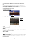
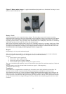
The Portaflow 216 is supplied with one (matched) pair of transducers and a single guiderail to measure flow. The
instrument selects the mode of operation (Reflex or Diagonal) dependant on the pipe size and flow velocity.
The instrument can be used over a range from 50mm to 400mm. In Reflex Mode the transducers are positioned in the
guide rail to assist correct alignment along the pipe axis,
(Figure 3)
. In Diagonal mode
(Figure 4)
the transducers are
removed from the rail and attached to the pipe using the gull-wings and chains. The pipe is then measured and marked
up and the transducer blocks are clipped to the pipe wall using a suitable amount of grease applied to the face of each
transducer.