


3
Select
Quick Start
- Press
ENTER
.
Dimension Units?
– Scroll to select units required, press
ENTER
.
Pipe OD
– Enter data, press
ENTER
.
Pipe Wall Thickness
– Enter data, press
ENTER.
Pipe Lining Thickness
– Enter data, press
ENTER
.
ENTER Zero
if there is no lining on the application.
Select Wall Material
– Select using scroll keys, press
ENTER
.
Select Lining Material
– This will only be displayed if a lining thickness has been entered. Select using the
scroll keys, press
ENTER
.
Select Fluid Type
– Select using scroll keys, press
ENTER
.
The instrument selects the mode of operation using the data entered and will display the following.
Attach sensor set
in XXXX mode
Approx. max. flow:
XXX m/s
Press ENTER to continue
Or SCROLL to change mode
Fluid Temp? Press Enter to
Input the application temperature in the units required °C or °F then press
ENTER.
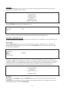
Now retract the sensor blocks back into the guide rail by turning the locking nuts clockwise.
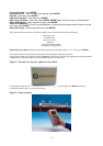
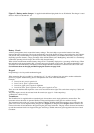
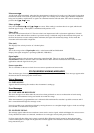
Apply grease to both sensor blocks as shown in
(Figure 1
)
, attach to the pipe using the appropriate mounting hardware
in either Reflex or Diagonal Mode. Ensure the Guide rail itself is free of grease
Figure 1:- Inverted view of grease applied to sensor block
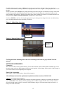
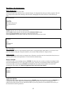
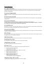
Connect the red and blue sensor cables to the electronics and the guide rail assembly. The
RED
cable must be
positioned upstream to give a positive flow reading.
Figure 2:- Sensor assembly